Eureka AIR delivers breakthrough ideas for toughest innovation challenges, trusted by R&D personnel around the world.

Internal formwork structure for elevator shaft and construction method

An elevator shaft and inner mold technology, which is applied in the direction of building structure support, building structure support, building structure support scaffolding, etc., can solve the problem that the elevator shaft does not meet the elevator installation standards, affects the forming quality of the elevator shaft body, and is difficult to install and dismantle formwork and other problems, to increase the number of template turnover, save manpower and material resources, and improve the effect of strength

Active Publication Date: 2019-04-19
德成建设集团有限公司
View PDF7 Cites 0 Cited by
  • Summary
  • Abstract
  • Description
  • Claims
  • Application Information

AI Technical Summary

Problems solved by technology

[0002] As the city develops faster and faster, and there are more and more high-rise buildings, elevators are widely used. The elevator shaft is the shaft for installing elevators. The size of the shaft is determined according to the type of elevator. Elevator tracks and counterweight tracks, the elevator wells reserved during the construction of civil works often do not meet the elevator installation standards, which requires the use of standard elevator well formwork to re-construct the reserved elevator wells in order to achieve the installation of elevators Standard, the traditional internal form support of elevator shafts in high-rise buildings is difficult to install and dismantle the formwork due to the many internal corners in the shaft, small plane size, and no retreat between the surrounding formwork. Especially
The removed formwork often needs to be hoisted to the ground for maintenance, which is labor-intensive and affects the forming quality of the elevator shaft

Method used


Image

  • Internal formwork structure for elevator shaft and construction method
  • Internal formwork structure for elevator shaft and construction method
  • Internal formwork structure for elevator shaft and construction method

Examples


Embodiment Construction

[0043] Preferred embodiments of the invention are described below with reference to the accompanying drawings. Those skilled in the art should understand that these embodiments are only used to explain the technical principles of the invention, and are not intended to limit the protection scope of the invention.

[0044] It should be noted that, in the description of the invention, terms such as "upper", "lower", "left", "right", "inner", "outer" and other indicated directions or positional relationships are based on the terms shown in the accompanying drawings. Orientation or positional relationship, which is only for convenience of description, and does not indicate or imply that the device or element must have a specific orientation, be constructed and operated in a specific orientation, and thus should not be construed as a limitation on the invention.

[0045]In addition, it should be noted that, in the description of the invention, unless otherwise clearly stipulated and...


PUM


Abstract

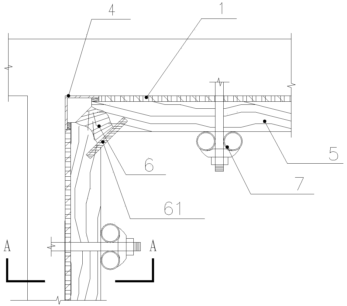
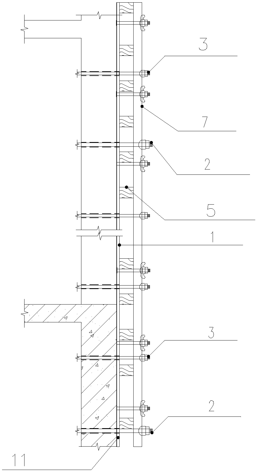
The invention provides an internal formwork structure for an elevator shaft and a construction method. The internal formwork structure comprises segmental formwork plates for constructing an internalformwork, internal corner steel angles for protecting the segmental formwork plates, wall penetrating bolts for positioning the segmental formwork plates, split bolts for supporting the segmental formwork plates, wood braces for reinforcing the segmental formwork plates, and double steel tubes for reinforcing the segmental formwork plates. The internal corner steel angles are located at internal corners of the elevator shaft and are connected with the segmental formwork plates; the wood braces arranged horizontally serve as secondary braces for the internal formwork structure, and contact withvertical wood brace plugs in an attached mode; the double steel tubes arranged vertically serve as primary braces for the internal formwork structure. The internal formwork structure has the advantages that the separate design of the formwork is based on the internal corner steel angles, the segmental formwork plates can be mounted and demounted easily, and the problem that the segmental formworkplates are easily damaged due to no avoidance position between the segmental formwork plates and surrounding formwork plates is solved effectively.

Description

technical field [0001] The invention relates to the construction field of an elevator shaft, in particular to an inner mold structure and a construction method for elevator shaft construction. Background technique [0002] As the city develops faster and faster, and there are more and more high-rise buildings, elevators are widely used. The elevator shaft is the shaft for installing elevators. The size of the shaft is determined according to the type of elevator. Elevator tracks and counterweight tracks, the elevator wells reserved during the construction of civil works often do not meet the elevator installation standards, which requires the use of standard elevator well formwork to re-construct the reserved elevator wells in order to achieve the installation of elevators Standard, the traditional internal form support of elevator shafts in high-rise buildings is difficult to install and dismantle the formwork due to the many internal corners in the shaft, small plane size,...

Claims


Application Information

Patent Timeline
Patent Type & Authority Applications(China)
IPC IPC(8): E04G3/24
Inventor 梁朋匡焰军沈洋辛长军李栋森张理进董子权尚高峰唐娅
Owner 德成建设集团有限公司
Why Eureka
Eureka Blog
Learn More