
Diffusion device for discharging waste water from ship tail gas desulfurization system

A diffusion device and desulfurization system technology, applied in water treatment devices, ship parts, ship construction, etc., can solve the problems of increased diffusion effect and system resistance, so as to reduce drainage resistance, effectively diffuse waste water, and reduce drainage obstruction interference Effect

Active Publication Date: 2019-04-19
上海蓝魂环保科技有限公司
View PDF5 Cites 0 Cited by
  • Summary
  • Abstract
  • Description
  • Claims
  • Application Information

AI Technical Summary

Problems solved by technology

[0009] The present invention aims at the technical problem that the "cross" type or star type diffusion device in the prior art causes the increase of the system resistance due to the increase of the diffusion effect, and the purpose is to provide an amplification device for the discharge of waste water from the ship tail gas desulfurization system

Method used

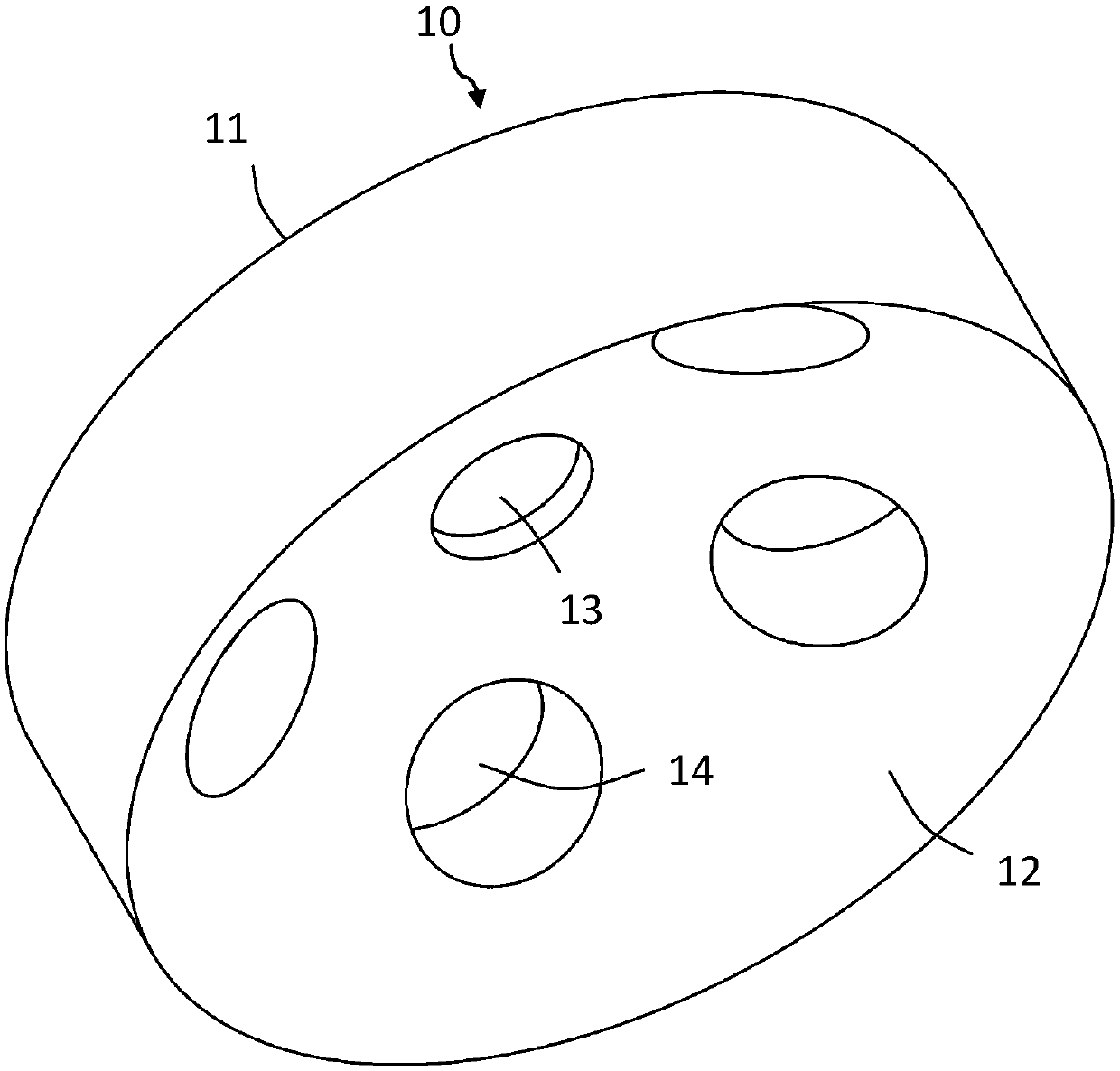
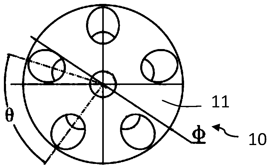
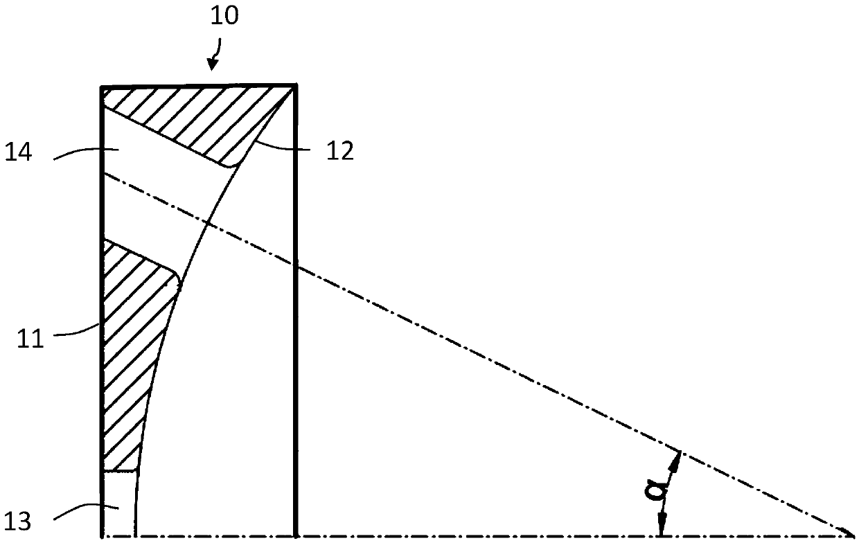

Image

  • Diffusion device for discharging waste water from ship tail gas desulfurization system
  • Diffusion device for discharging waste water from ship tail gas desulfurization system
  • Diffusion device for discharging waste water from ship tail gas desulfurization system

Examples


Embodiment 1

[0056] The inner diameter of the drainage pipe is 400mm, and the drainage flow is 600m 3 / h, the pH value of the drainage is 2.6. Diffuse the drain dilution using the following diffuser. The diameter of the diffusion device is 400mm, the radius of the inner arc of the concave surface 12 is 280mm, one central diffusion hole with a diameter of 40mm; six peripheral diffusion holes with a diameter of 60mm respectively, the elevation angle а of the holes is 28°, and the angle θ between the holes is 60° ; The central thickness of the cylindrical body is 12mm respectively. The rounding radius of the inner side of each round hole is 8mm. Under this structure, the pH value of the drainage can reach 6.7 at a distance of 4 meters from the outlet from the outlet of 2.6. The resistance level of the structural system is 32kpa, and the setting of the diffusion device significantly improves the dilution effect of the washing wastewater discharge, making the washing wastewater easily meet t...

Embodiment 2

[0058] The inner diameter of the drainage pipe is 300mm, and the drainage flow is 680m 3 / h, the pH value of the drainage is 2.6. Diffuse the drain dilution using the following diffuser. The diameter of the diffuser is 300mm, the inner arc radius of the concave surface 12 is 240mm, and 6 drainage holes are arranged on the arc surface. There is 1 central diffusion hole with a diameter of 50mm; 5 peripheral diffusion holes with a diameter of 70mm each, the hole elevation angle а is 30°, and the angle θ between holes is 72°; the central thickness of the cylindrical body is 10mm. The fillet radius of the inner side of each round hole is 6mm. Under this structure, the pH value of the drainage can reach 6.6 at a distance of 4 meters from the water outlet from 2.6 to the water outlet, and the resistance of the diffuser will be 40kpa in this structure.


PUM


Abstract

The invention discloses a diffusion device for discharging waste water from a ship tail gas desulfurization system. The diffusion device comprises a cylindrical body, wherein a plane, a concave surface, a central diffusion hole and a plurality of peripheral diffusion holes are formed in the cylindrical body. The central diffusion hole and a plurality of the peripheral diffusion holes are formed inthe cylindrical body, and a certain hole elevation angle is arranged between the central line of the peripheral diffusion holes and the axis of the cylindrical body, so that waste water diffused by the peripheral diffusion holes rapidly diffuses to the peripheral direction, the mutual concentration superposition of waste water diffusion is less; waste water discharged by a plurality of the peripheral holes diffuses out along the respective peripheral directions, and thus drainage obstruction interference between the peripheral diffusion holes can be reduced, and the drainage resistance can bewell reduced, so that the diffusion device can achieve the purpose of effectively diffusing waste water under lower resistance and meet the requirements of IMO MPEC.

Description

technical field [0001] The invention belongs to the technical field of ship tail gas washing, in particular to a diffusion device for discharging waste water from a ship tail gas desulfurization system. Background technique [0002] With the development of the international shipping industry and ocean-going shipping, exhaust emissions from ships have become the main source of pollution in coastal areas. The pollution of the atmospheric environment caused by SOX in the exhaust gas of ships has aroused widespread concern in the international community. At present, ship exhaust gas scrubbing and desulfurization systems (EGCS) are mainly divided into wet scrubbing and desulfurization systems, which almost occupy the entire ship scrubbing and desulfurization market. [0003] There are three different implementation forms of the ship flue gas wet scrubbing system: ① seawater scrubbing exhaust gas (open system), using the alkalinity of seawater to absorb SO in the exhaust gas X ,...

Claims


Application Information

Patent Timeline
Patent Type & Authority Applications(China)
IPC IPC(8): B63J4/00
CPCB63J4/00
Inventor 曹建涛汪浩王地何炜孙毅良程宏
Owner 上海蓝魂环保科技有限公司
Learn More