Eureka AIR delivers breakthrough ideas for toughest innovation challenges, trusted by R&D personnel around the world.
Injection mold for auto parts
What is Al technical title?
Al technical title is built by PatSnap Al team. It summarizes the technical point description of the patent document.
A technology for injection molds and auto parts, used in household appliances, household components, other household appliances, etc., can solve the problems of polluted working environment, lack of convenient replacement of mold cores, and reduced mold practicability.
Active Publication Date: 2021-07-16
佛山锐海汽车零部件有限公司
View PDF7 Cites 0 Cited by
Summary
Abstract
Description
Claims
Application Information
AI Technical Summary
This helps you quickly interpret patents by identifying the three key elements:
Problems solved by technology
Method used
Benefits of technology
Problems solved by technology
[0003] The currently used injection molds have certain defects, such as the lack of a convenient replacement function for the mold core. The mold core is generally fixed inside the mold shell, which is inconvenient to replace the mold core, which reduces the practicability of the mold. At the same time, the mold shell lacks a leak-proof mechanism. When the mold shell is injected, the injection material will flow out from the circular through hole, polluting the working environment
Method used
Image
Click on the blue label to locate the original text in one second.
Reading with bidirectional positioning of images and text.
Examples
Embodiment Construction
[0024] The following will clearly and completely describe the technical solutions in the embodiments of the present invention with reference to the accompanying drawings in the embodiments of the present invention. Obviously, the described embodiments are only some, not all, embodiments of the present invention. Based on the embodiments of the present invention, all other embodiments obtained by persons of ordinary skill in the art without making creative efforts belong to the protection scope of the present invention.
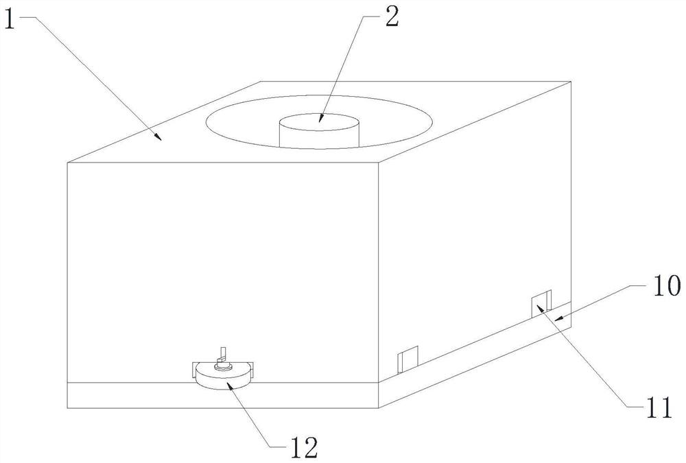
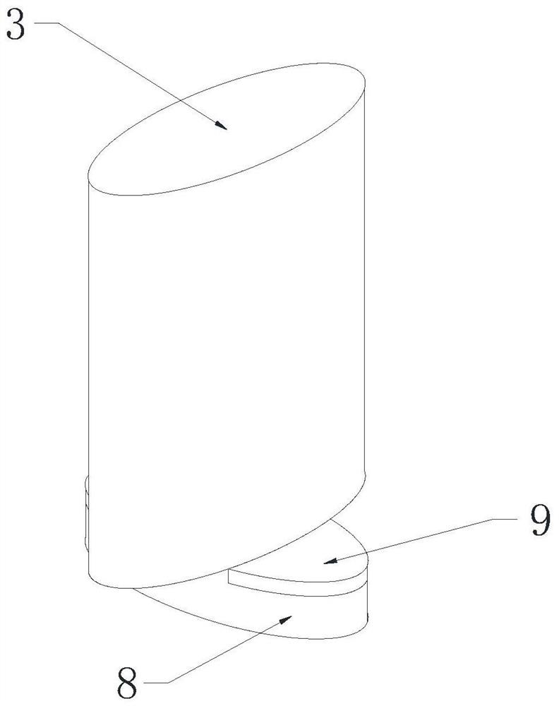
[0025] see Figure 1-5 As shown, an injection mold for automobile parts includes a mold shell 1, a mold core 2, a replacement mechanism for replacing the mold core, and a leak-proof mechanism to prevent the mold from leaking out. The mold core 2 is installed at the inner bottom of the mold shell 1 ;
[0026] The replacement mechanism includes an upper rod 3, a reset coil spring 4, a rotating rod 5, a bearing 6, a circular groove 7, a lower rod 8 and a magneti...
PUM
Abstract
The invention belongs to the technical field of moulds, specifically an injection mold for automobile parts, including a mold shell, a mold core, an upper rod, a return coil spring, a rotating rod, a bearing, a circular groove, a lower rod, a magnetic block, a leak-proof shell, Racks, gears, magnetic rings, moving rods, tie rods, springs, and fixed rods. The invention rotates the lower rod, the rotation of the lower rod drives the rotating rod to rotate around the bearing, and the rotation of the rotating rod increases the elastic potential energy of the return coil spring. Inside the through slot, loosen the lower rod, and under the action of the elastic potential energy of the return coil spring, the lower rod rotates back to its original position. At this time, the magnetic block fits the mold shell, and then the installation of the mold core is completed. The moving rod moves to drive the magnetic ring Move, the magnetic ring moves and the gear is separated, the moving rod moves to compress the spring, the spring is compressed to generate elastic force, the rack moves to drive the gear to rotate, loosen the pull rod, and under the action of the spring force, the magnetic ring returns to its original position and fits the gear .
Description
technical field [0001] The invention belongs to the technical field of moulds, in particular to an injection mold for auto parts. Background technique [0002] In the mold industry, various molds and tools are used for injection molding, blow molding, extrusion, die-casting or forging forming, smelting, stamping and other methods to obtain the required products. In short, a mold is a tool used to make a molded product. This tool is composed of various parts, and different molds are composed of different parts. It mainly realizes the processing of the shape of the article through the change of the physical state of the formed material. [0003] The currently used injection molds have certain defects, such as the lack of a convenient replacement function for the mold core. The mold core is generally fixed inside the mold shell, which is inconvenient to replace the mold core and reduces the practicability of the mold. At the same time, the mold shell lacks a leak-proof mechani...
Claims
Application Information
Patent Timeline
Application Date:The date an application was filed.
Publication Date:The date a patent or application was officially published.
First Publication Date:The earliest publication date of a patent with the same application number.
Issue Date:Publication date of the patent grant document.
PCT Entry Date:The Entry date of PCT National Phase.
Estimated Expiry Date:The statutory expiry date of a patent right according to the Patent Law, and it is the longest term of protection that the patent right can achieve without the termination of the patent right due to other reasons(Term extension factor has been taken into account ).
Invalid Date:Actual expiry date is based on effective date or publication date of legal transaction data of invalid patent.