
Device for leg movement of ICU patient

A technology for legs and patients, which is applied in the field of devices for ICU patients' legs, which can solve the problems of high labor intensity for medical staff or patients' families, affecting recovery and normal walking, consuming physical strength and time, and avoiding slow blood circulation. , the effect of normal blood circulation in the feet and low cost

Active Publication Date: 2019-04-19
SICHUAN PROVINCIAL PEOPLES HOSPITAL
View PDF13 Cites 14 Cited by
  • Summary
  • Abstract
  • Description
  • Claims
  • Application Information

AI Technical Summary

Problems solved by technology

[0002] ICU patients lie on the hospital bed and keep one posture for a long time (the supine posture is the majority). Because the patient cannot take care of himself and needs to stay in one posture for a long time, the patient lies down for a long time, which will easily affect the blood circulation of the patient's lower limbs, resulting in edema. Time inactivity will lead to atrophy of leg muscles and ligaments, and the internal function of the whole body will also deteriorate, which will also affect the later recovery and normal walking. At present, the nursing staff or the patient's family members usually hold the patient's leg with their hands and repeat the bending movement , and it takes a certain amount of time to be effective, but this requires the nursing staff to consume a lot of physical strength and time, and also requires the nursing staff to grasp the strength to avoid hurting the patient, so this method of artificially assisted movement is more troublesome and not enough Convenient, resulting in high labor intensity for medical staff or patients' families

Method used


Image

  • Device for leg movement of ICU patient
  • Device for leg movement of ICU patient

Examples


Embodiment Construction

[0017] A specific embodiment of the present invention will be described in detail below in conjunction with the accompanying drawings, but it should be understood that the protection scope of the present invention is not limited by the specific embodiment.

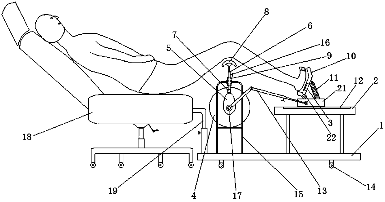
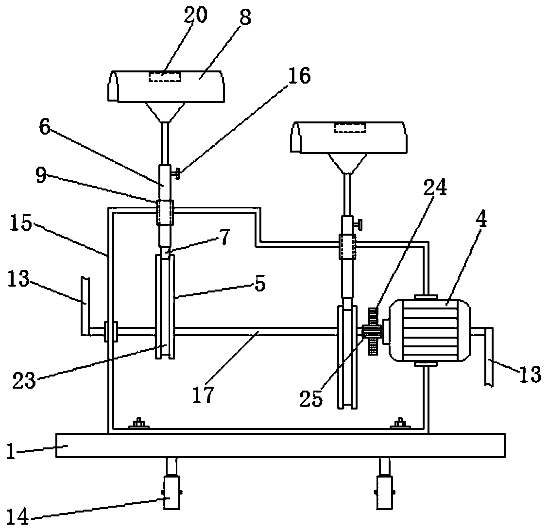
[0018] Such as figure 1 , figure 2 As shown, the embodiment of the present invention provides a kind of device for the leg activity of ICU patient, comprises base plate 1, and the left side on described base plate 1 is fixed with frame body 15, is provided with rotating shaft 17 on frame body 15, on rotating shaft 17 Two leg movement mechanisms corresponding to the left and right legs of the ICU patient are connected side by side to make their legs curl up and stretch; the leg movement mechanism includes an eccentric cam 5 that is pivotally connected to the rotating shaft 17 through a key, The ridge of the eccentric cam 5 is provided with a T-shaped chute 23 around the eccentric cam 5 circumferential direction, the T-sha...


PUM


Abstract

The invention discloses a device for leg movement of an ICU patient. A frame body of a bottom plate of the device is provided with a rotating shaft, and two leg movement mechanisms corresponding to the left and right legs of the ICU patient and allowing the legs to curl and stretch are connected with the rotating shaft side by side; the leg movement mechanisms comprise eccentric cams in shaft connection with the rotating shaft, the protruding edges of the eccentric cams are provided with T-shaped sliding grooves around the circumferences of the eccentric cams, the T-shaped sliding grooves areslidably connected with T-shaped sliding blocks, the T-shaped sliding blocks are connected with the lower ends of lifting rods, the upper ends of lifting rods are provided with leg supporting bodies,the lifting rods are further sleeved with guiding cylinders, and the guiding cylinders are fixed on the frame body; the rotating shaft is further in shaft connection with a first gear, the first gearis meshed with a second gear, the second gear is connected with an output shaft of a motor, the motor is fixed on the frame body, and the motor is electrically connected with a power source through amotor controller. The device for the leg movement of the ICU patient can drive the legs of the patient to rhythmically curl and stretch, thereby moving the legs, the structure is simple, and the production cost is low.

Description

technical field [0001] The invention relates to the field of medical equipment, in particular to a device for moving legs of ICU patients. Background technique [0002] ICU patients lie on the hospital bed and keep one posture for a long time (the supine posture is the majority). Because the patient cannot take care of himself and needs to stay in one posture for a long time, the patient lies down for a long time, which will easily affect the blood circulation of the patient's lower limbs, resulting in edema. Time inactivity will lead to atrophy of leg muscles and ligaments, and the internal function of the whole body will also deteriorate, which will also affect the later recovery and normal walking. At present, the nursing staff or the patient's family members usually hold the patient's leg with their hands and repeat the bending movement , and it takes a certain amount of time to be effective, but this requires the nursing staff to consume a lot of physical strength and t...

Claims


Application Information

Patent Timeline
IPC IPC(8): A61H1/02A61H23/02A61F7/00
CPCA61F7/007A61F2007/0045A61F2007/0071A61H1/0218A61H1/0255A61H23/02A61H2201/0149A61H2205/10
Inventor 张晓勤卢森潘灵爱贺宏丽吴潇潇雷雨罗晓秀李天龙刘荣安黄晓波黎嘉嘉王艺萍
Owner SICHUAN PROVINCIAL PEOPLES HOSPITAL
Learn More