Power hop anticipation and mitigation

A signal and threshold technology, applied in transportation and packaging, external condition input parameters, control devices, etc., can solve problems such as component wear or failure

Active Publication Date: 2019-04-16
KELSEY HAYES CO
View PDF9 Cites 0 Cited by
  • Summary
  • Abstract
  • Description
  • Claims
  • Application Information

AI Technical Summary

Problems solved by technology

These tire sags can lead to undesirable NVH (noise, vibration, harshness) characteristics, excessive component wear or failure of drivetrain and suspension components

Method used


Image

  • Power hop anticipation and mitigation
  • Power hop anticipation and mitigation
  • Power hop anticipation and mitigation

Examples


Embodiment Construction

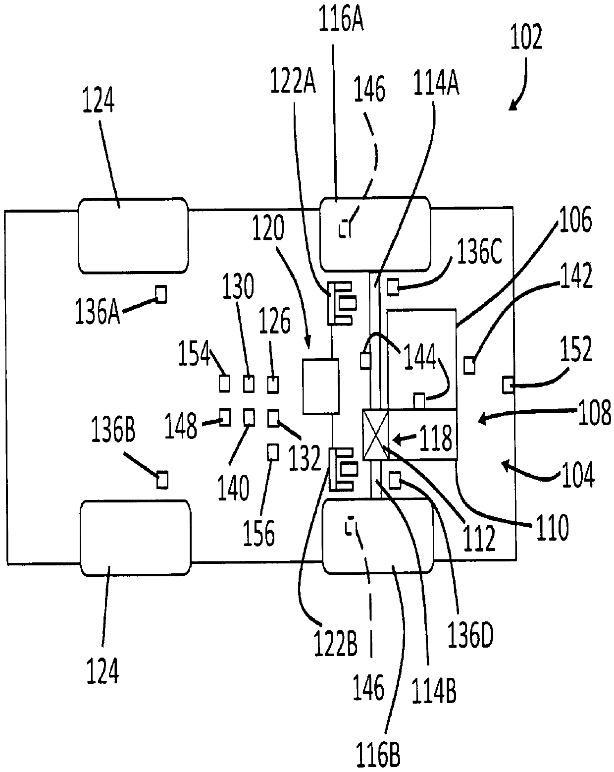
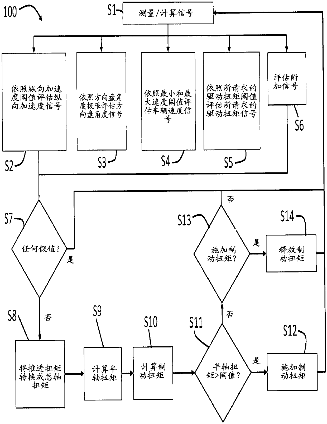
[0015] Reference now Figure 1 to Figure 5 , A control method 100 for predicting and reducing the resonance of a vehicle (usually indicated by 102) is shown. Vehicle 102 in figure 1 It is shown schematically and has a powertrain, usually indicated by 104. The powertrain 104 has a power source 106, such as an internal combustion engine, an electric motor, or other power generating devices for generating torque of the engine or the electric motor.

[0016] The powertrain 104 also has a power transmission system generally indicated by 108, which is connected to the power source 106 and receives engine torque. In the illustrated embodiment, the powertrain 108 is configured as a variable speed differential that includes a transmission 110 and a differential 112. The powertrain 108 is shown in the context of a front-wheel drive (FWD) powertrain, but other powertrain configurations are considered to be within the scope of the present invention. For example, the power transmission sys...


PUM


Abstract

Longitudinal acceleration, intended travel angle, wheel speed, and requested drive torque signals are measured for a vehicle. The longitudinal acceleration, intended travel angle, wheel speed, and requested drive torque signals are then evaluated. A brake torque is calculated as a function of a propulsive torque, wherein the propulsive torque is produced by a power source for the vehicle. The brake torque is applied when the longitudinal acceleration signal exceeds a longitudinal acceleration threshold, the intended travel angle signal is between intended travel angle limits, the wheel speed signal is less than a minimum speed threshold, the requested drive torque signal exceeds a requested drive torque threshold, and a torque threshold is exceeded.

Description

[0001] Cross reference of related applications [0002] This application claims the priority and rights of U.S. Provisional Application Serial No. 62 / 367,167 filed on July 27, 2016, the entire disclosure of which is incorporated herein by reference Background technique [0003] The present invention generally relates to a vehicle brake system, and in particular, to an operating method for a vehicle brake system for reducing resonance (excited by periodically changing longitudinal force) (power hop) and a power transmission system in advance. vibration. [0004] The automobile includes a powertrain that transmits torque from a power source to the driven wheels of the vehicle. For example, the power source may be an internal combustion engine that transmits torque to a transmission or an electric motor connected to drive wheels. The power transmission system transmits torque to the power wheels. The power transmission system usually includes a shaft or half shaft that drives a drive...

Claims


Application Information

Patent Timeline
Patent Type & Authority Applications(China)
IPC IPC(8): B60W30/20B60W40/107B60W40/105
CPCB60T8/175B60T8/17555B60W30/18172B60T2210/36B60W2510/0657B60W2510/0661B60W2520/10B60W2520/105B60W2540/10B60W2540/18B60W2540/30B60W2710/182B60W30/20B60W2040/1307B60W2520/28B60W2510/182B60W2510/1005B60W2540/215B60W2520/30B60W2710/18B60W2552/40B60W2555/20B60W2520/125B60T8/171B60T8/172B60T8/3205B60T8/58B60T2210/124B60T2210/30B60T2240/00B60T2250/04B60T2270/20B60W10/06B60W10/184B60W2510/10B60W2530/20B60W2710/0666
Inventor D·S·康C·B·米切尔
Owner KELSEY HAYES CO
Why Eureka
Try Eureka