
Display panel and manufacturing method thereof and method for driving display panel

A display panel and controller technology, applied in static indicators, optics, instruments, etc., can solve problems such as poor display effect

Active Publication Date: 2019-04-16
BOE TECH GRP CO LTD
View PDF4 Cites 13 Cited by
  • Summary
  • Abstract
  • Description
  • Claims
  • Application Information

AI Technical Summary

Problems solved by technology

For this reason, an object of the present invention is to propose a method that can realize real-time compensation for the outgoing light of the light-emitting element of the pixel unit, overcome the defect of poor display effect caused by aging or defects in the working process, and enable A display panel that can still achieve better display effect after a long time, has a simple structure, does not need to change the overall structure, is easy to realize in technology, or is easy to industrialize production

Method used


Image

  • Display panel and manufacturing method thereof and method for driving display panel
  • Display panel and manufacturing method thereof and method for driving display panel
  • Display panel and manufacturing method thereof and method for driving display panel

Examples


Embodiment Construction

[0034] Embodiments of the present invention are described in detail below. The embodiments described below are exemplary only for explaining the present invention and should not be construed as limiting the present invention. If no specific technique or condition is indicated in the examples, it shall be carried out according to the technique or condition described in the literature in this field or according to the product specification. The reagents or instruments used were not indicated by the manufacturer, and they were all commercially available conventional products.

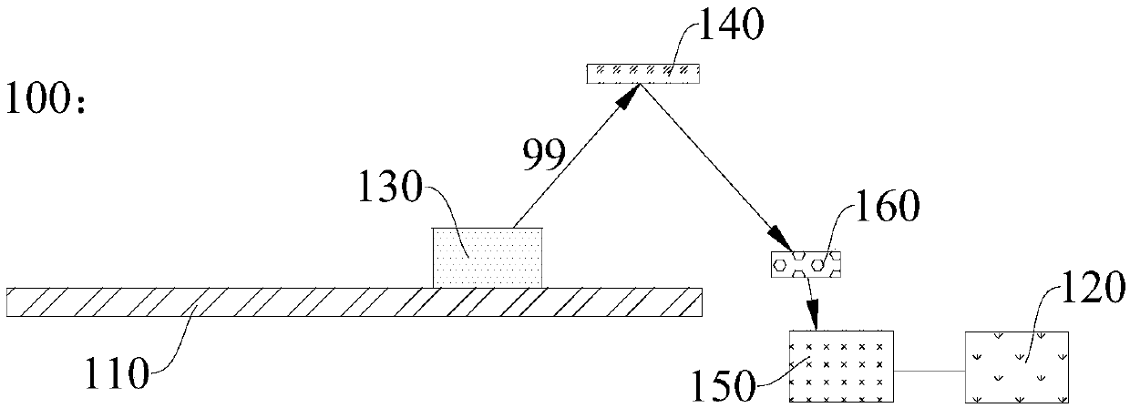
[0035] In one aspect of the invention, the invention provides a display panel. According to an embodiment of the present invention, refer to figure 1, the display panel 100 includes an array substrate 110 and a controller 120, and the array substrate 110 has a plurality of pixel units (it should be noted that, for the convenience of description, in figure 1 Only one pixel unit is shown in ; In addition,...


PUM


Abstract

The invention provides a display panel and a manufacturing method thereof and a method for driving the display panel. The display panel comprises an array substrate and a controller, wherein a plurality of pixel units are arranged on the array substrate; light-emitting elements are arranged in the pixel units; reflective layers and optical sensors electrically connected with the controller are arranged in at least a part of the pixel units; the reflective layers are arranged in the light-emitting directions of the light-emitting elements and used for reflecting the emergent light emitted fromthe light-emitting elements to the optical sensors; the optical sensors are used for measuring the real-time intensity of the reflected light; and the controller is used for adjusting the light-emitting intensity of the light-emitting elements to approach the theoretical intensity according to the real-time intensity. The display panel has the beneficial effects that the real-time compensation ofthe emergent light emitted from the light-emitting elements of the pixel units can be realized; the defect of poor display effect due to aging or badness is overcome; a good display effect can still be realized after long-time use; and the structure is simple and the overall structure of the display panel needs not to be changed, so that the display panel is easy to realize in process and the industrial production is easy.

Description

technical field [0001] The present invention relates to the field of display technology, in particular, to a display panel, a manufacturing method thereof, and a method for driving the display panel. Background technique [0002] In the related art, after the display panel is put into use, poor display will be caused due to defective array (array substrate) or aging; in addition, as the use time of the display panel increases, different pixels will have different aging degrees, which will also lead to poor display. At present, the method to solve the above-mentioned poor display is mainly to use the CCD (electrical coupling device) to perform a pixel (pixel)-level precise optical calibration directly after the Gamma (gamma) debugging is performed when the display panel leaves the factory; The external circuit of the panel performs external circuit compensation to compensate for the shift of Vth (threshold voltage). However, none of the aforementioned methods can realize the...

Claims


Application Information

Patent Timeline
IPC IPC(8): H01L27/32G02F1/1333G02F1/133G09G3/3208G09G3/36G02F1/1335
CPCG02F1/13318G02F1/1333G02F1/133553G09G3/3208G09G3/36G09G2320/0626G09G2320/046H10K59/60G09G2360/145G09G3/006G09G2320/0233H10K59/13G02F1/13338H10K50/856H10K59/65H10K71/00
Inventor 黄清雨焦志强闫华杰张娟李晓虎
Owner BOE TECH GRP CO LTD
Learn More