Method for determining sheet stamping springback compensation factor

A technology of springback compensation and thin plate stamping, which is applied in the field of thin plate stamping springback, can solve the problems that the simulation results are not completely reliable and the prediction accuracy is not very high, and achieve the effect of reliable springback data and improved accuracy

Inactive Publication Date: 2019-04-16
HARBIN UNIV OF SCI & TECH
View PDF5 Cites 6 Cited by
  • Summary
  • Abstract
  • Description
  • Claims
  • Application Information

AI Technical Summary

Problems solved by technology

[0003] Although several versions have been updated and iterated, as far as the widely used finite element numerical simulation software is concerned at this stage, its prediction accuracy is not very high (≤75%), and the simulation results it provides are not completely reliable.

Method used


Image

  • Method for determining sheet stamping springback compensation factor
  • Method for determining sheet stamping springback compensation factor
  • Method for determining sheet stamping springback compensation factor

Examples


specific Embodiment approach 1

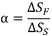
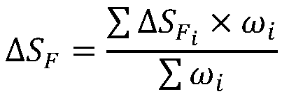
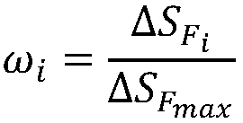
[0032] Specific implementation mode 1: A method for determining the springback compensation factor of thin plate stamping in this embodiment, the method for determining the springback compensation factor of thin plate stamping can be realized by the following steps:

[0033] Step 1: According to the geometric dimensions of the designed mold, reverse solve the standard stamping parts, that is, the geometric dimensions of the ideal parts without springback;

[0034] Step 2: According to the geometric dimensions of the standard stamping parts obtained by the reverse solution, in the computer, use 3D drawing software to establish the model of the standard stamping parts;

[0035] Step 3: Import the model of the established standard stamping part into the finite element numerical simulation software for mesh division to obtain a meshed finite element model;

[0036] Step 4: Record the spatial position of each node in the finite element model of the obtained standard stamping parts,...

specific Embodiment approach 2

[0055] Specific embodiment 2: Different from specific embodiment 1, in the method for determining the springback compensation factor of thin plate stamping in this embodiment, the calculation of the offset distance of each corresponding node as described in step 6 and step 11 requires the use of finite elements Utilities tools for numerical simulation software.

specific Embodiment approach 3

[0056] Embodiment 3: Different from Embodiment 1, in this embodiment, a method for determining the springback compensation factor of thin plate stamping uses the same type and specification of blanks and the same set of molds for the three trial stampings described in step 8.


PUM


Abstract

The invention discloses a method for determining a sheet stamping springback compensation factor. The method comprises: firstly, a standard stamping part model is established according to the die size; importing the model into numerical simulation software to carry out stamping springback simulation; calculating the offset distance between the part profile subjected to springback simulation and the corresponding node of the standard stamping part model, and substituting the result and the offset distance between the part profile subjected to actual stamping and the corresponding node of the standard stamping part model into a compensation factor calculation formula for calculation to finally obtain the springback compensation factor. The compensation factor obtained through the method canhelp the numerical simulation software to improve the precision of the springback compensation function of the numerical simulation software, so that a more reasonable mold is manufactured, the mold testing frequency is remarkably reduced, and the production efficiency is improved.

Description

technical field [0001] The invention relates to the field of thin plate stamping springback, in particular to a method for determining a compensation factor for thin plate stamping springback. Background technique [0002] Springback is one of the common defects in sheet metal stamping deformation, and the springback phenomenon restricts the development of sheet metal stamping. How to accurately estimate the amount of springback in sheet metal stamping so as to effectively reduce springback has gradually attracted widespread attention in the industry. The advent of finite element numerical simulation software provides a very convenient tool for people to predict the springback direction of parts and estimate the amount of springback, which improves the quality and dimensional accuracy of products. [0003] Although several versions have been updated and iterated, as far as the finite element numerical simulation software widely used at the present stage is concerned, its pr...

Claims


Application Information

Patent Timeline
Patent Type & Authority Applications(China)
IPC IPC(8): G06F17/50
CPCG06F30/23
Inventor 刘晓晶潘景昊
Owner HARBIN UNIV OF SCI & TECH
Why Eureka
Try Eureka