Suspension bracket device of electric suspension test bed

An electric suspension and bracket device technology, applied in the direction of railway vehicle testing, can solve problems such as unfavorable promotion and lack of invention, and achieve the effects of easy installation, disassembly and maintenance, simplified structure, and wide range of applicable working conditions.

Active Publication Date: 2019-04-16
CO WITH LTD LIABILITY OF MEDICAL SCI
View PDF6 Cites 2 Cited by
  • Summary
  • Abstract
  • Description
  • Claims
  • Application Information

AI Technical Summary

Problems solved by technology

[0004] The prior art (application number: CN205800824U) discloses a coil type permanent magnet electric levitation device for maglev trains, and the prior art (application number: CN105109360B) discloses a static levitation device for permanent magnet electric maglev trains. device, however, there are few researches on permanent magnet electric levitation technology at home and abroad at present, and the invention of permanent magnet electric levitation technology test is still relatively lacking. There is no relatively easy-to-implement device to verify the theoretical research results of this technology, which is not conducive to Promotion of this technology

Method used


Image

  • Suspension bracket device of electric suspension test bed
  • Suspension bracket device of electric suspension test bed
  • Suspension bracket device of electric suspension test bed

Examples


no. 1 example

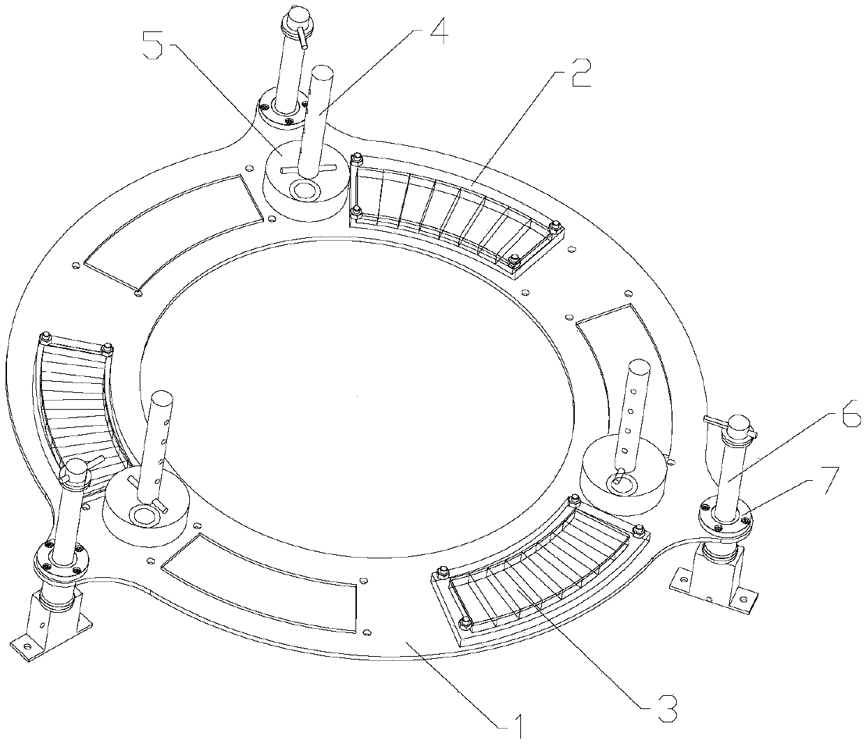
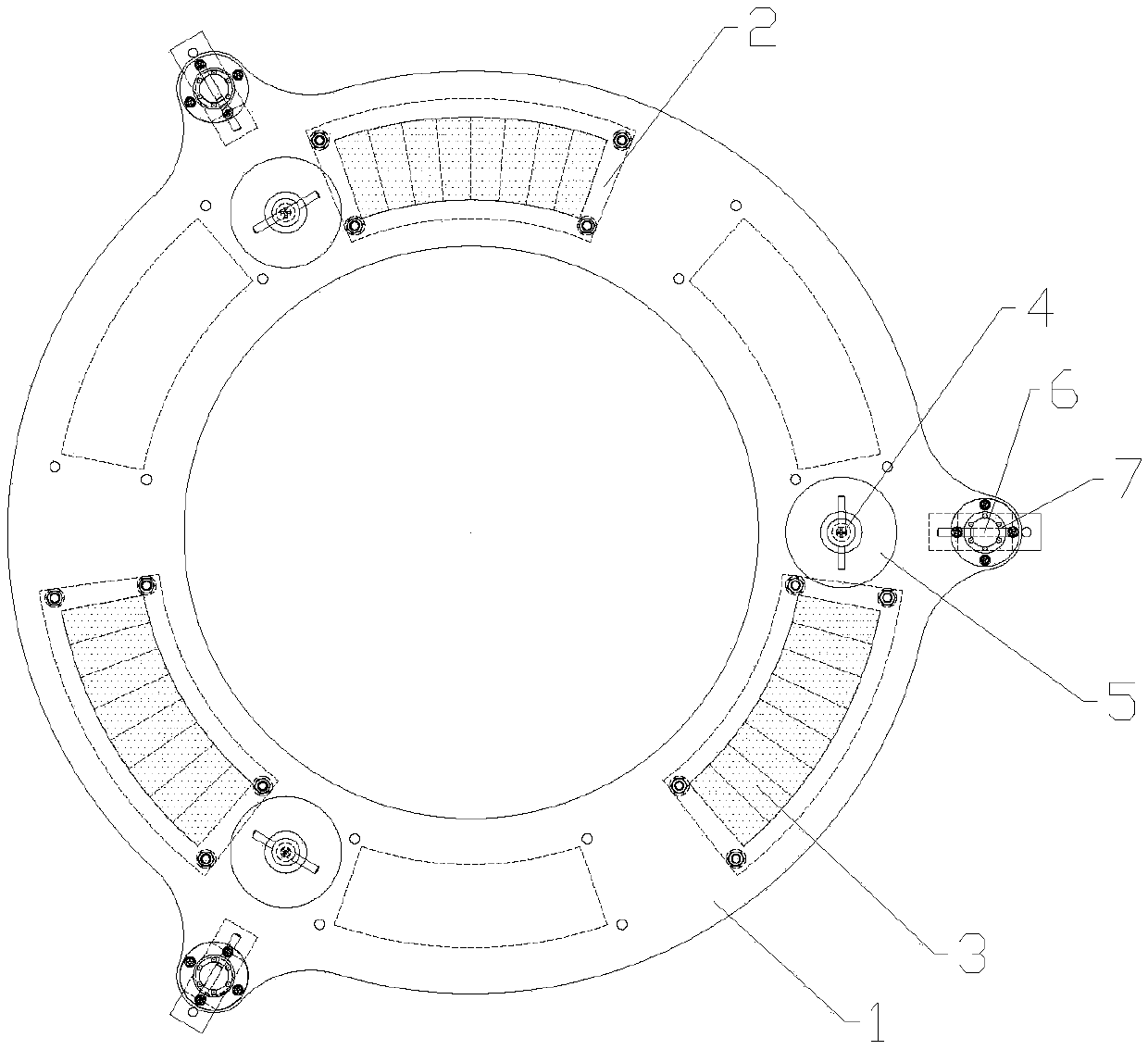
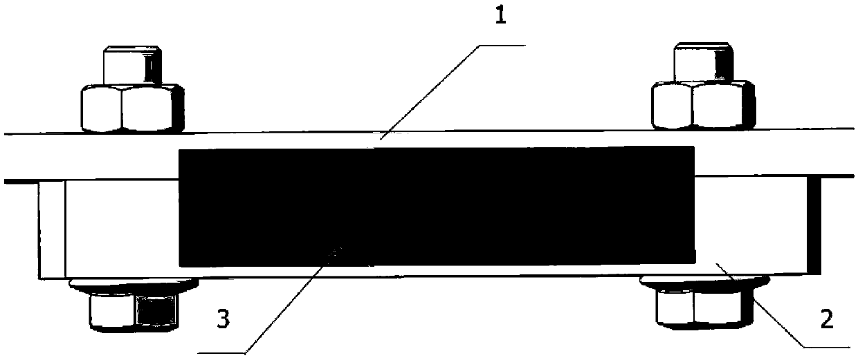
[0032] Please refer to figure 1 , the present embodiment provides a suspension bracket device for an electric suspension test bench, which includes a suspension frame and a guide rod 6 fixed on the suspension test bench, and the suspension frame includes a suspension tray 1, a permanent magnet shell 2, an annular permanent magnet 3, The counterweight column 4, the counterweight block 5 and the linear bearing 7; the suspension tray 1, the permanent magnet shell 2 and the counterweight rod are made of lightweight aluminum alloy, and the guide rod 6 is made of stainless steel; the top of the suspension tray 1 is installed with a counterweight column 4. It is used to add counterweights 5 of different weights. The permanent magnet shell 2 is installed at the bottom of the suspension tray 1, and a ring-shaped permanent magnet 3 is placed inside it. The linear bearing 7 is arranged at the edge of the suspension tray 1 to guide The rod 6 is fixed on the test bench through the mounting...

no. 2 example

[0040] Please refer to Figure 5 , the present embodiment provides a suspension bracket device for an electric suspension test bench, which includes a suspension frame and a guide rod 6 fixed on the suspension test bench, and the suspension frame includes a suspension tray 1, a permanent magnet shell 2, an annular permanent magnet 3, The counterweight column 4, the counterweight block 5 and the linear bearing 7; the suspension tray 1, the permanent magnet shell 2 and the counterweight rod are made of lightweight aluminum alloy, and the guide rod 6 is made of stainless steel; the top of the suspension tray 1 is installed with a counterweight column 4. It is used to add counterweights 5 of different weights. The permanent magnet shell 2 is installed at the bottom of the suspension tray 1, and a ring-shaped permanent magnet 3 is placed inside it. The linear bearing 7 is arranged at the edge of the suspension tray 1 to guide The rod 6 is fixed on the test bench through the mountin...

no. 3 example

[0049] Please refer to Figure 7 , the present embodiment provides a suspension bracket device for an electric suspension test bench, which includes a suspension frame and a guide rod 6 fixed on the suspension test bench, and the suspension frame includes a suspension tray 1, a permanent magnet shell 2, an annular permanent magnet 3, The counterweight column 4, the counterweight block 5 and the linear bearing 7; the suspension tray 1, the permanent magnet shell 2 and the counterweight rod are made of lightweight aluminum alloy, and the guide rod 6 is made of stainless steel; the top of the suspension tray 1 is installed with a counterweight column 4. It is used to add counterweights 5 of different weights. The permanent magnet shell 2 is installed at the bottom of the suspension tray 1, and a ring-shaped permanent magnet 3 is placed inside it. The linear bearing 7 is arranged at the edge of the suspension tray 1 to guide The rod 6 is fixed on the test bench through the mountin...


PUM


Abstract

The invention discloses a suspension bracket device of an electric suspension test bed. The suspension bracket device comprises a suspension tray, a permanent magnet shell, an annular permanent magnet, a balance weight column, a balance weight block, a linear bearing and a guide rod. The annular permanent magnet is packaged in the suspension tray through the permanent magnet shell, the balance weight column is connected to the suspension tray, the balance weight block is installed on the balance weight column, the linear bearing is installed on the suspension tray, and the guide rod is inserted into a bearing hole of the linear bearing and can slide relative to the guide rod; the guide rod is fixed on the test bed through a mounting block at the bottom of the guide rod, the guide rod is inserted through a bearing hole of the linear bearing, the linear bearing can slide relative to the guide rod, the suspension frame performs a suspension experiment of moving in the linear direction through the linear bearing and the guide rod, and when the device is mounted on the horizontal test bed, the suspension tray moves in the vertical direction and suspends. The device can solve the problems that inventions are insufficient in the aspect of permanent magnet electric suspension technology tests and the theoretical research result of the technology cannot be verified, and the popularization of the technology is facilitated.

Description

technical field [0001] The invention relates to the technical field of permanent magnet electric levitation trains, in particular to a levitation bracket device of an electric levitation test bench. Background technique [0002] The maglev train realizes the non-contact suspension and guidance between the train and the track through electromagnetic force, and at the same time uses the traction force generated by the traction motor on the train to move forward. The levitation system of the maglev train is the core of the maglev train technology, which is divided into three types: electromagnetic levitation, permanent maglev levitation and electric levitation. [0003] Permanent magnetic electric levitation technology is the product of the combination of permanent magnetic levitation and electric levitation. When the permanent magnet keeps a certain distance on the induction plate and moves at a certain relative speed, an induced eddy current will be generated in the inductio...

Claims


Application Information

Patent Timeline
Patent Type & Authority Applications(China)
IPC IPC(8): G01M17/08
CPCG01M17/08
Inventor 马卫华康凯宁韩亚鹏
Owner CO WITH LTD LIABILITY OF MEDICAL SCI
Why Eureka
Try Eureka