Device for eliminating infrared image grid lines of micrometering bolometer, and elimination method thereof

A technology of microbolometer and infrared image, which is applied in measuring devices, radiation pyrometry, optical radiometry, etc., can solve problems such as blurred images, a lot of money and time, and difficult quality requirements for digital image capture devices , to achieve the effect of low cost and elimination of image grid noise

Inactive Publication Date: 2019-04-16
NANJING UNIV OF SCI & TECH
View PDF6 Cites 0 Cited by
  • Summary
  • Abstract
  • Description
  • Claims
  • Application Information

AI Technical Summary

Problems solved by technology

[0006] The first way is to improve the production process to improve the quality of the optical sensor and the alignment accuracy of the lens and the optical sensor. However, improving the production process often requires a lot of money and time, and even if the production process is improved It is also difficult to guarantee that every digital image capture device produced can meet the quality requirements
[0007] The second method is to use image processing to remove the grid noise of the Bell image, that is, each original G-value pixel and its adjacent G-value pixels can be weighted and averaged, and the weighted average can be used as the pixel The G value of the point, which eliminates the imbalance of the G value, also eliminates the grid noise, but the above method may cause the original image to be blurred, especially at the edge of the original image

Method used


Image

  • Device for eliminating infrared image grid lines of micrometering bolometer, and elimination method thereof
  • Device for eliminating infrared image grid lines of micrometering bolometer, and elimination method thereof
  • Device for eliminating infrared image grid lines of micrometering bolometer, and elimination method thereof

Examples


Embodiment Construction

[0022] The present invention will be described in further detail below in conjunction with the accompanying drawings.

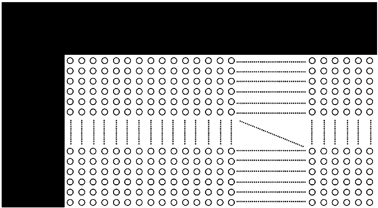
[0023] The device for eliminating the grid pattern of the infrared image of the microbolometer according to the present invention uses a right-angle metal plate to shield the edge of the microbolometer, so that the external radiation cannot radiate to the shielded part, and at the same time, the unshielded The integral voltage (output voltage) of the shaded part is subtracted from the integral voltage (output voltage) of the shaded part to obtain the voltage difference, and finally the voltage difference is output as the pixel voltage. Its system design diagram is as follows figure 1 Shown:

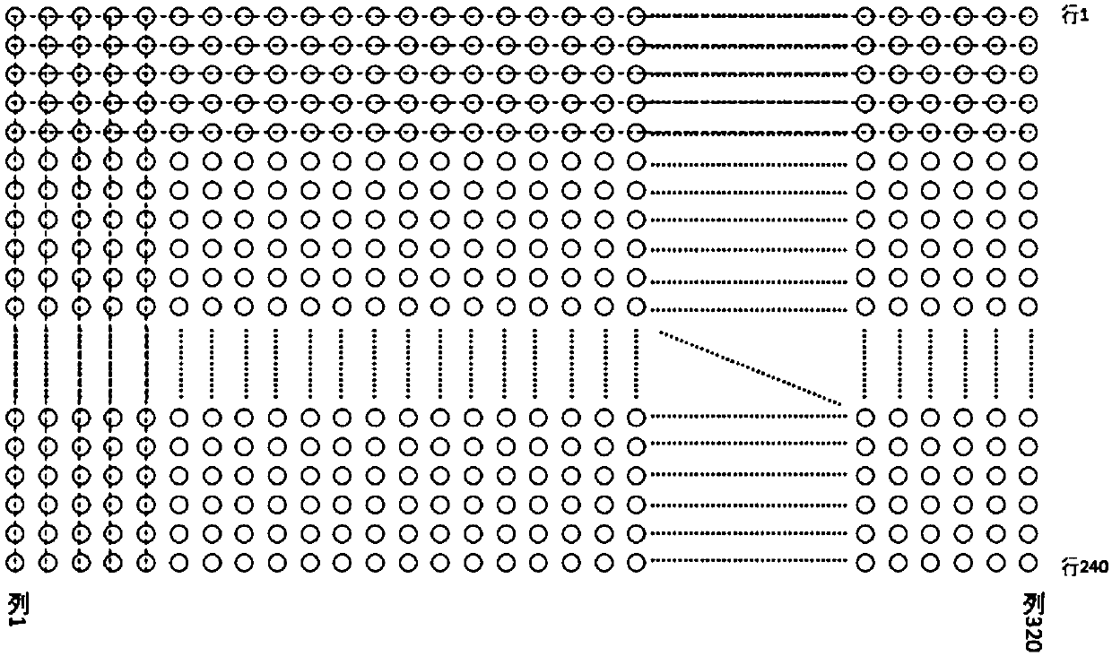
[0024] Such as figure 1 and figure 2 As shown, it is a focal plane array (FPA) of a 320*240 microbolometer, and a right-angle metal plate is used to block 5 rows*5 columns from the upper left corner of the microbolometer.

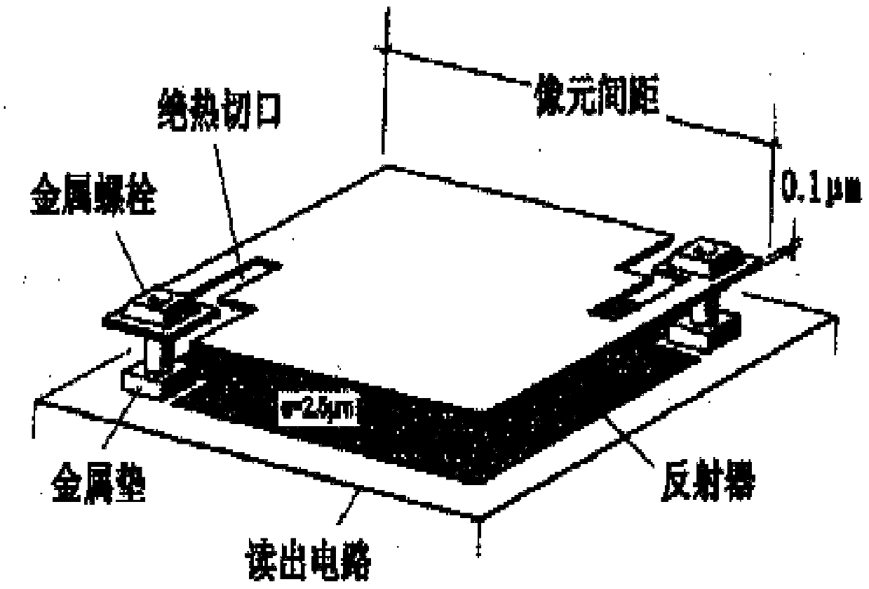
[0025] Each pixel structure is as image ...


PUM


Abstract

The invention discloses a device for eliminating infrared image grid lines of a micrometering bolometer, and an elimination method thereof. Five lines*five rows of pixels at a left upper corner of themicrometering bolometer is shielded by using a right-angle metal plate, and the output voltage of each unshielded pixel point subtracts the average value of the output votlages of the shielded pixelpoints at the same line and same row.

Description

technical field [0001] The invention belongs to the field of microbolometers, and in particular relates to a device and a method for eliminating grid patterns in infrared images of microbolometers. Background technique [0002] The microbolometer with temperature T is a thermal infrared sensor. In order to measure the thermal effect after absorbing infrared heat radiation, the sensor uses a material whose temperature depends on the change of resistance R(T). At present, the research on the noise characteristics of the microbolometer is only limited to the variation trend of the noise with the bias voltage, but in the present invention, the noise caused by the different amplification factors of the column amplifiers is also considered. [0003] Because the pixel voltage is obtained by row integration, there is a certain error in the bias voltage of each row, and the bias voltage controls the sampling of the system, resulting in different values ​​of the pixel voltage obtained...

Claims


Application Information

Patent Timeline
IPC IPC(8): G01J5/06G01J5/20
CPCG01J5/06G01J5/20
Inventor 隋修宝李龙顾国华蔡思聪何伟基刘郭新陈扬罗璐瑶
Owner NANJING UNIV OF SCI & TECH
Why Eureka
Try Eureka