A connecting device for hanging plates in a deep foundation pit supporting structure
A deep foundation pit support and connection device technology, which is applied in infrastructure engineering, construction, excavation, etc., can solve problems such as inability to conveniently locate and install, and achieve the effects of avoiding freeze-thaw cycles, compact overall structure, and firm connection
- Summary
- Abstract
- Description
- Claims
- Application Information
AI Technical Summary
Problems solved by technology
Method used
Image
Examples
Embodiment 1
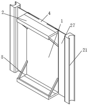
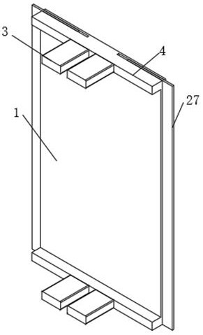
[0029] A connection device for hanging plates in a deep foundation pit support structure, comprising a main body support frame 1, the front side of the upper and lower ends of the main body support frame 1 is fixedly connected to the rear side of a pressure-bearing connection shell 4, and the front side of the pressure-bearing connection shell 4 is connected to the bearing The rear side of the pressure horizontal plate 2 is fixedly connected, the left and right sides of the front end of the pressure horizontal plate 2 are fixedly connected with the front end of the fixed bracket 5, the rear end of the fixed bracket 5 is fixedly connected with the left and right ends of the front side of the main support frame 1, and the inside of the pressure horizontal plate 2 The left and right sides of the middle are fixedly equipped with a pressure-bearing protective shell 3, and the left and right sides of the main body support frame 1 are provided with limiting grooves 28, and the moving p...
Embodiment 2
[0031] Embodiment 2: the difference based on Embodiment 1 is;
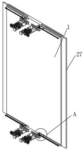
[0032] The transmission mechanism includes: a motor 6, a rotating gear 7, a rotating cylinder 8, a limit block 9, a rotating wheel 10, a transmission gear 11 and a transmission shaft 12, a motor 6 is fixedly installed on the left side of the inner front end of the pressure-bearing protection shell 3, and the main shaft of the motor 6 The upper part is fixedly installed with a rotating gear 7, a limit block 9 and a rotating cylinder 8 sequentially from front to back, the rear end of the main shaft of the motor 6 is movably connected with the front side of the pressure-bearing protection shell 3, and the right side of the rotating gear 7 is meshed with the left side of the rotating wheel 10. , the right side of the front end of the rotating wheel 10 is meshed with the transmission gear 11, the axis of the transmission gear 11 is fixedly connected with the front side of the transmission shaft 12, the front end of the ...
Embodiment 3
[0035] Embodiment 3: the difference based on embodiment 1 and 2 is;
[0036] The lateral movement mechanism includes: rotating helical gear 13, transmission helical gear 14, screw mandrel 15, moving block 16, connecting rod 17, bearing 18 and fixed rod 19, the front end of transmission shaft 12 is fixedly connected with rotating helical gear 13 axle centers, and the rotation The left side of the helical gear 13 is meshed with the front side of the transmission helical gear 14, the axis of the transmission helical gear 14 is fixedly connected with the left side of the screw rod 15, the left end of the screw rod 15 is flexibly connected with the rear end of the fixed rod 19, and the front end of the fixed rod 19 is connected The inner front end of the connecting shell 4 is fixedly connected, the right end of the screw rod 15 is fixedly connected with the shaft center of the bearing 18, the bearing 18 is fixedly connected with the inner right end of the pressure-bearing connection...
PUM
 Abstract
Description
Claims
Application Information
 - R&D
- Intellectual Property
- Life Sciences
- Materials
- Tech Scout
- Unparalleled Data Quality
- Higher Quality Content
- 60% Fewer Hallucinations
Browse by: Latest US Patents, China's latest patents, Technical Efficacy Thesaurus, Application Domain, Technology Topic, Popular Technical Reports.
© 2025 PatSnap. All rights reserved.Legal|Privacy policy|Modern Slavery Act Transparency Statement|Sitemap|About US| Contact US: help@patsnap.com


