
Flight control method and system and unmanned aerial vehicle

A technology for unmanned aerial vehicles and flight control, applied in the fields of unmanned aerial vehicles, systems, and flight control methods, can solve problems such as crashes, unmanned aerial vehicle crashes, and insufficient battery power to support unmanned aerial vehicles to continue flying, and achieve guaranteed The effect of flying safety and reducing the probability of crash

Active Publication Date: 2019-04-16
SZ DJI TECH CO LTD
View PDF5 Cites 1 Cited by
  • Summary
  • Abstract
  • Description
  • Claims
  • Application Information

AI Technical Summary

Problems solved by technology

During the actual flight, due to the continuous consumption of the battery power of the UAV, it often happens that the battery power is not enough to support the continued flight of the UAV
[0004] In order to avoid the safety hazard of the unmanned aerial vehicle crash caused by continuous control of the unmanned aerial vehicle flight due to the user not knowing the battery power consumption, most unmanned aerial vehicles currently provide a battery power reminder method to remind the user Current remaining battery power
[0005] However, in practical applications, such a situation often occurs: when the user controls the flight of the UAV, it is easy to ignore the low battery prompt and still control the flight of the UAV. For the sake of protecting the battery, when the battery power is lower than a certain threshold, the battery The management system cut off the battery output, causing the crash
To sum up, at present, under the condition of low battery, unmanned aerial vehicles still have hidden dangers in safe flight

Method used


Image

  • Flight control method and system and unmanned aerial vehicle
  • Flight control method and system and unmanned aerial vehicle
  • Flight control method and system and unmanned aerial vehicle

Examples


Embodiment Construction

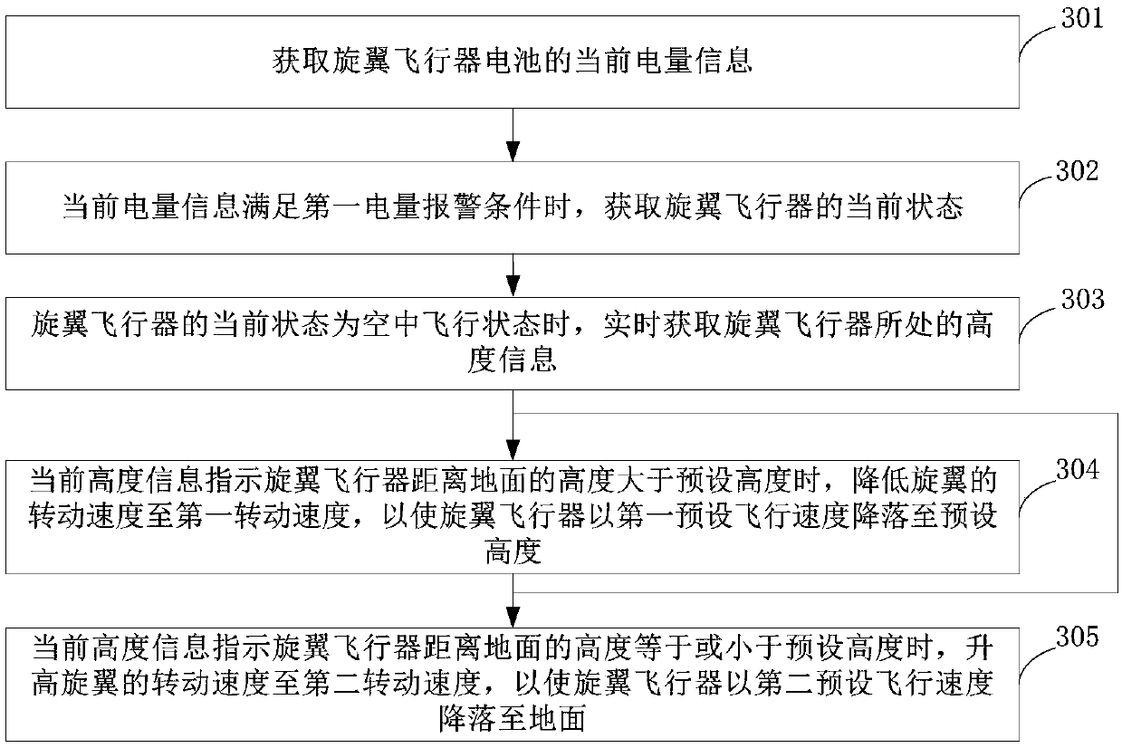
[0062] In order to make the purpose, technical solutions and advantages of the embodiments of the present invention clearer, the technical solutions in the embodiments of the present invention will be clearly and completely described below in conjunction with the drawings in the embodiments of the present invention. Obviously, the described embodiments It is a part of embodiments of the present invention, but not all embodiments. Based on the embodiments of the present invention, all other embodiments obtained by persons of ordinary skill in the art without making creative efforts belong to the protection scope of the present invention.

[0063] The solution of the present invention will be described in detail below in conjunction with several specific embodiments, wherein the solutions provided by the following method embodiments can be executed by the flight control unit in the unmanned aerial vehicle or commonly referred to as a processor.

[0064] figure 1 The flow chart ...


PUM


Abstract

The invention discloses a flight control method and system and an unmanned aerial vehicle. The method includes the steps that current electricity quantity information (101) of a battery of the unmanned aerial vehicle is obtained; when the current electricity quantity information meets a first electricity quantity alarming condition, the current state (102) of the unmanned aerial vehicle is obtained; according to the current state of the unmanned aerial vehicle, the unmanned aerial vehicle is controlled to be in a corresponding safe protection mode, and when the current state is an aerial flight state, the unmanned aerial vehicle is controlled to be in a landing state; if the current state is a non-lift-off state, the unmanned aerial vehicle is controlled to be in a shutdown mode (103). When it is detected that the unmanned aerial vehicle is under a low-electricity quantity condition, the unmanned aerial vehicle is controlled to be in the safe protection mode corresponding to the current state, in this way, the flight safety of the unmanned aerial vehicle is guaranteed, and the probability of crash of the unmanned aerial vehicle is lowered.

Description

[0001] This application is a divisional application with the application number 201680003238.7, the application date is March 1, 2016, and the invention title is flight control method, system and unmanned aerial vehicle. technical field [0002] Embodiments of the present invention relate to the field of unmanned aerial vehicles, and in particular to a flight control method, system and unmanned aerial vehicle. Background technique [0003] Unmanned aerial vehicles such as drones have been widely used in fields such as aerial photography and reconnaissance. During the actual flight, due to the continuous consumption of the battery power of the unmanned aerial vehicle, it often happens that the battery power is not enough to support the continued flight of the unmanned aerial vehicle. [0004] In order to avoid the safety hazard of the unmanned aerial vehicle crash caused by continuous control of the unmanned aerial vehicle flight due to the user not knowing the battery power ...

Claims


Application Information

Patent Timeline
IPC IPC(8): B64D27/24B64C19/00G05D1/00
CPCB64C19/00B64D27/24G05D1/00G05D1/04Y02T50/60
Inventor 许柏皋王雷王文韬田杰罗昊
Owner SZ DJI TECH CO LTD
Learn More