Wing mechanism, emitter and method for shortening axial length thereof
A launcher and wing technology, applied in the aviation field, can solve problems such as unfavorable carrying, carrying, non-adjustable wing length, long launch tube length, etc., to achieve the effects of improving convenience, shortening the overall length, and reducing maintenance costs
- Summary
- Abstract
- Description
- Claims
- Application Information
AI Technical Summary
Problems solved by technology
Method used
Image

Examples
Embodiment 1
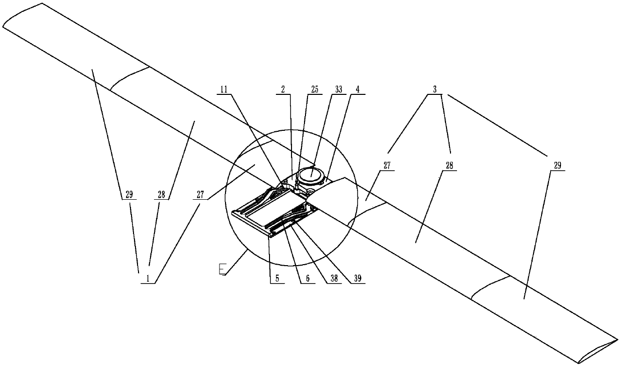
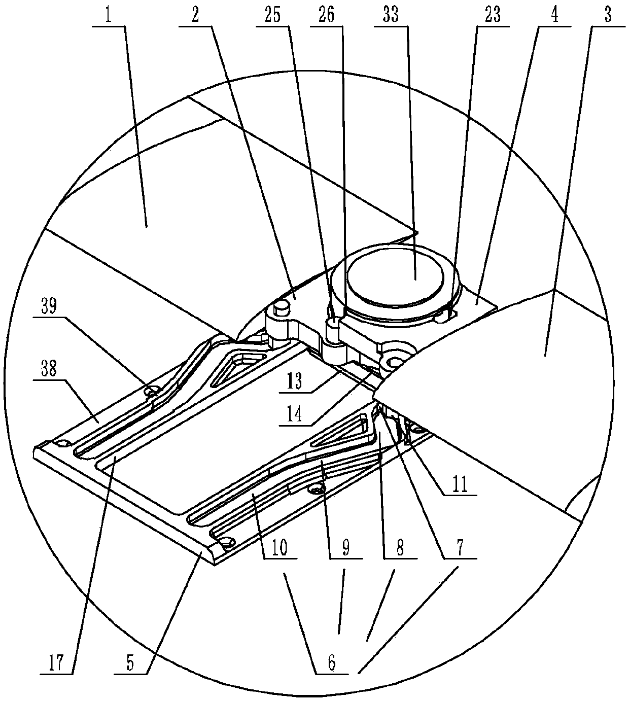
[0060] Such as Figure 1-Figure 15 As shown, a wing mechanism of the present invention includes a support assembly, a right plate 2 connected to the root of the right wing 1 and a left plate 4 connected to the root of the left wing 3, and the right plate 2 and the left plate 4 are far away from One side of the corresponding wing root is rotatably connected with the upper surface of the support assembly, and a slide plate 5 is slidably arranged at the bottom of the support assembly, and the sliding direction of the support assembly on the slide plate 5 is parallel to the flying direction of the wing. On the slide plate 5 and on one side of the moving direction of the support assembly, a chute 6 is provided, and the chute 6 includes a positioning section 7, a steering section 8, an oblique push section 9 and a limiting section that are sequentially connected in an arc and have uniform widths and dimensions. Section 10, the extension direction of the positioning section 7 is para...
Embodiment 2
[0072] This embodiment is an implementation description of the sliding connection between the support assembly and the slide plate 5 .
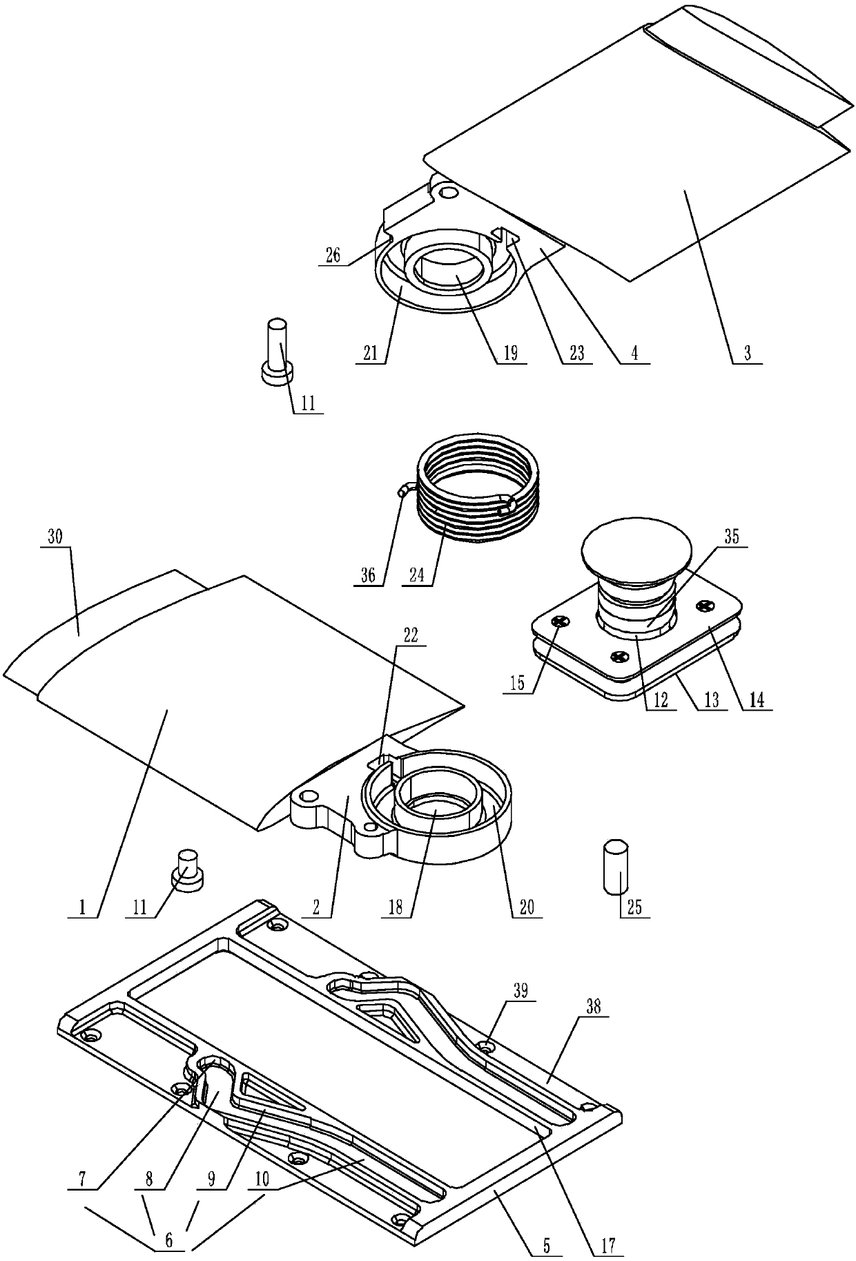
[0073] Such as Figure 1-Figure 7 As shown, a wing mechanism of the present invention is provided with a strip-shaped through-hole 17 on the slide plate 5, and the long side of the cross-section of the strip-shaped through-hole 17 is parallel to the flying direction of the wing;
[0074] The support assembly includes a base assembly and a hinge shaft 12 connected in sequence, and the base assembly includes a base plate 13, a positioning plate 14 and several screws 15, and the base plate 13 and the positioning plate 14 are all parallel to the slide plate 5, and are located on the slide plate respectively. 5 below and above, one end of the hinge shaft 12 is connected with the bottom plate 13, and the other end of the hinge shaft 12 passes through the strip-shaped through hole 17 and the positioning plate 14 successively, and is connected with t...
Embodiment 3
[0079] This embodiment is an implementation description of the hinge between the support assembly and the wing.
[0080] Such as Figure 1-Figure 7 As shown, a wing mechanism of the present invention also includes a hook-shaped cylindrical helical compression spring 24, a right through hole 18 cooperating with the hinge shaft 12 is provided on the right plate 2, and a right through hole 18 matched with the hinge shaft 12 is provided on the upper surface of the right plate 2. The right annular groove 20 coaxial with the right through hole 18 is provided with a right locking groove 22 communicating with the right annular groove 20 on the upper surface of the right plate 2 near the side of the right wing 1, and the right plate 2 passes through the right through hole 18 is sleeved on the hinge shaft 12;
[0081] The left plate 4 is provided with a left through hole 19 cooperating with the hinge shaft 12, and the lower surface of the left plate 4 is provided with a left annular groo...
PUM
 Abstract
Description
Claims
Application Information
 - R&D
- Intellectual Property
- Life Sciences
- Materials
- Tech Scout
- Unparalleled Data Quality
- Higher Quality Content
- 60% Fewer Hallucinations
Browse by: Latest US Patents, China's latest patents, Technical Efficacy Thesaurus, Application Domain, Technology Topic, Popular Technical Reports.
© 2025 PatSnap. All rights reserved.Legal|Privacy policy|Modern Slavery Act Transparency Statement|Sitemap|About US| Contact US: help@patsnap.com