
Running gear structure and gear vehicle wheel set

A gear structure and gear technology, applied in the field of rail transit vehicles, can solve the problems of shortened wheel life, high life cycle cost, cumbersome disassembly process, etc., to achieve good replaceability, save maintenance time and cost, and improve Economical effect

Pending Publication Date: 2019-04-16
CRRC ZIYANG CO LTD
View PDF0 Cites 5 Cited by
  • Summary
  • Abstract
  • Description
  • Claims
  • Application Information

AI Technical Summary

Problems solved by technology

The wear of the wheel tread is limited, which greatly shortens the life of the wheel, and the cost of the whole life cycle of the vehicle is high
[0004] If the running gear fails or the wear of the wheel diameter exceeds the limit, the wheel set needs to be disassembled, replaced or repaired. The disassembly process is cumbersome, the cost is high, and the maintainability is poor.

Method used


Image

  • Running gear structure and gear vehicle wheel set
  • Running gear structure and gear vehicle wheel set
  • Running gear structure and gear vehicle wheel set

Examples


Embodiment 1

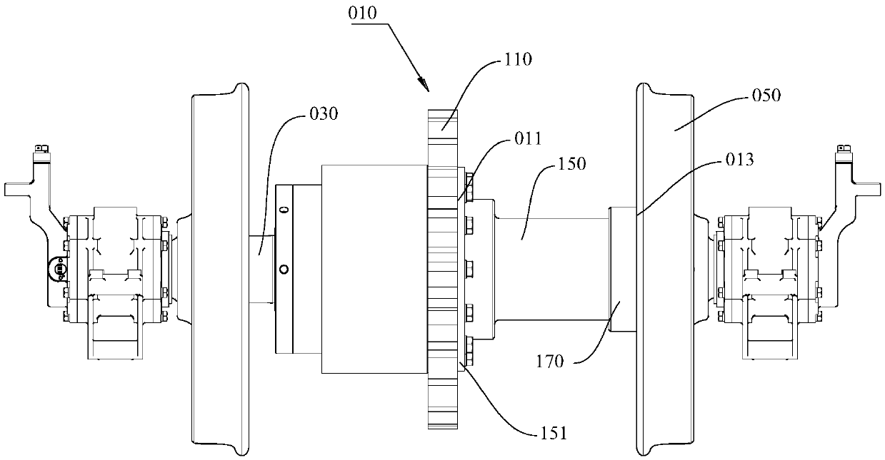
[0033] This embodiment provides a traveling gear structure 010, please refer to figure 1 with figure 2 , this traveling gear structure 010 includes a first half ring gear 110, a second half ring gear 130 and a gear hub 150;

[0034] The gear hub 150 includes an axial first end 011 and a second end 013;

[0035] see Figure 5 , the first end 011 of the gear hub 150 is provided with a first mounting part, and the second half ring gear 130 and the first half ring gear 110 are provided with a second mounting part; through the first mounting part and the second mounting part Cooperate so that the first half ring gear 110 and the second half ring gear 130 are installed on the first end 011 of the gear hub 150, and the first half ring gear 110 and the second half ring gear 130 are fixed on the gear hub 150 to form a circle Shaped integral gear.

[0036] see image 3 with Figure 4 , in this embodiment, the first mounting part is the first mounting plate 151 protruding radially...

Embodiment 2

[0044] This embodiment provides a wheel set for a geared vehicle, please refer to figure 1 with figure 2 , this traveling gear structure 010 includes an axle 030, a wheel 050 and the traveling gear structure 010 in the first embodiment;

[0045] The axle 030 passes through the installation through hole 015, and the axle 030 and the gear hub 150 are in interference connection, and the wheels 050 are fixedly arranged at both ends of the axle 030.

[0046] In order to further fix the gear hub 150 and the axle shaft 030, a third mounting part (not shown) is also arranged on the axle shaft 030, the third mounting part is a third mounting plate, and a third fixing channel is provided on the third mounting plate hole, the gear hub 150 is provided with a fourth mounting piece, the fourth mounting piece is a fourth mounting plate, and the fourth mounting plate is provided with a fourth fixing through hole corresponding to the third fixing through hole, through which the bolt passes t...


PUM


Abstract

The invention provides a running gear structure and a gear vehicle wheel set, and belongs to the field of rail transit vehicles. The running gear structure comprises a first half ring gear, a second half ring gear and a gear hub; the gear hub is provided with a first mounting member, and the second half ring gear and the first half ring gear are provided with second mounting members respectively;the first half ring gear and the second half ring gear are fixed on the gear hub to be combined into an integral gear; the axis of the gear hub is further provided with a mounting through hole used for cooperating with an axle. The running gear structure and the gear vehicle wheel set have the advantages that a plurality of split ring gear sets with different pitch diameters can be predesigned, and after wheel running abrasion reaches the meshing tolerance limitation of a running gear and rack, another split ring gear set with an adaptive pitch circle replaces the corresponding split gear set,so that the wheel service life can be prolonged by about 4 times, and the economical efficiency of vehicle use is improved.

Description

technical field [0001] The invention relates to the field of rail transit vehicles, in particular to a traveling gear structure and a gear vehicle wheel set. Background technique [0002] The running gears on the wheel sets of existing rack railway vehicles at home and abroad are almost all integral gears, which are installed in the middle of the wheel set through interference or bolts. In the assembly sequence, the running gear must be installed first, then the middle part of the axle shaft, and finally the wheels at both ends. The wheels are press-fitted onto the axles with interference, requiring specific press-fitting equipment and complex processes. [0003] During the operation of the rack vehicle, the wheels on both sides have tread wear, and the diameter of the wheel becomes smaller accordingly. At the same time, the wheel and the running gear are installed on the same axis, and the meshing relationship between the gear and the rack will change with the diameter of...

Claims


Application Information

Patent Timeline
IPC IPC(8): B61B13/02B61C9/00
CPCB61B13/02B61C9/00
Inventor 陈清建
Owner CRRC ZIYANG CO LTD
Learn More