
Force sensor for polishing robot

A technology of force sensor and robot, which is applied in the direction of grinding machine parts, grinding/polishing equipment, workpiece feed movement control, etc. It can solve the problems of measurement error and inability to accurately measure grinding pressure, etc., and improve measurement accuracy Effect

Inactive Publication Date: 2019-04-16
北京季融网络科技有限公司
View PDF6 Cites 1 Cited by
  • Summary
  • Abstract
  • Description
  • Claims
  • Application Information

AI Technical Summary

Problems solved by technology

[0004] In the prior art, the force sensor is only simply fixed between the robot and the grinding wheel, and the friction between the grinding wheel and the workpiece will generate a larger moment when grinding, and a certain amount will be generated when the grinding wheel rotates. The centrifugal force, so the force sensor will bear the action of other forces except the grinding pressure, resulting in a certain error in the measurement
[0005] Therefore, we propose a force sensor for grinding robots to solve the problem that the grinding pressure cannot be accurately measured in the prior art

Method used

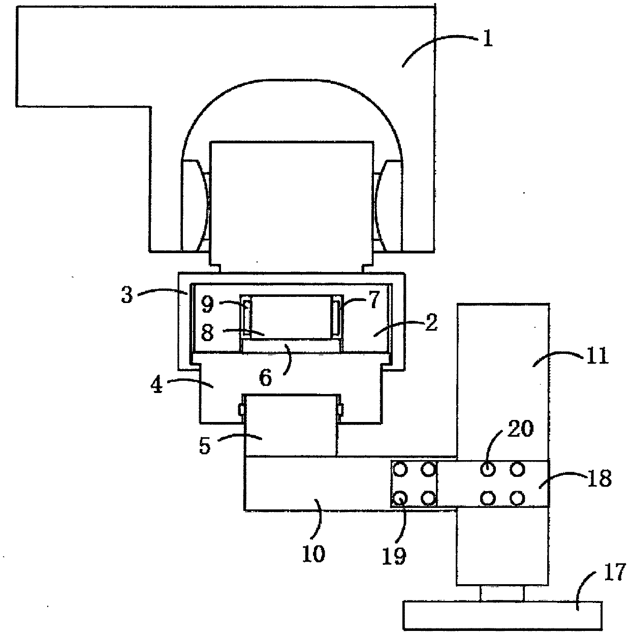

Image

  • Force sensor for polishing robot
  • Force sensor for polishing robot
  • Force sensor for polishing robot

Examples


Embodiment Construction

[0026] The following will clearly and completely describe the technical solutions in the embodiments of the present invention with reference to the accompanying drawings in the embodiments of the present invention. Obviously, the described embodiments are only some, not all, embodiments of the present invention.

[0027] In describing the present invention, it should be understood that the terms "upper", "lower", "front", "rear", "left", "right", "top", "bottom", "inner", " The orientation or positional relationship indicated by "outside", etc. is based on the orientation or positional relationship shown in the drawings, and is only for the convenience of describing the present invention and simplifying the description, rather than indicating or implying that the referred device or element must have a specific orientation, so as to Specific orientation configurations and operations, therefore, are not to be construed as limitations on the invention.

[0028] refer to Figure ...


PUM


Abstract

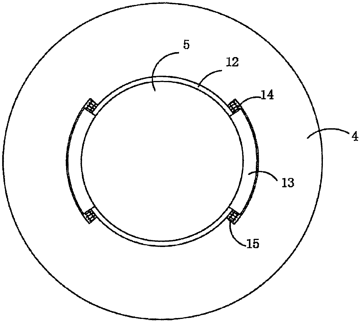
The invention discloses a force sensor for a polishing robot. The force sensor comprises a force sensor device fixedly connected to a robot arm, and the force sensor device is fixedly connected with the robot arm through a sensor fixing seat; a mounting groove is formed in the sensor fixing seat, and the force sensor device is fixedly connected to the inner top of the mounting groove; the lower end of the force sensor device is fixedly connected with an inverted-T-shaped force-bearing panel, and the lower end of the inverted-T-shaped force-bearing panel penetrates through the sensor fixing seat and is connected with a supporting plate through a cylindrical connecting body which is fixedly connected with the supporting plate; and the lower end of the inverted-T-shaped force-bearing panel isprovided with a cylindrical groove, wherein the cylindrical connecting body is clamped in the cylindrical groove in a matched mode. The force sensor is compact in structure and convenient to operate,the force sensor device is conveniently mounted between the robot arm and a polishing mechanism, meanwhile, force in other directions is counteracted through a mechanical structure, and thus the polishing pressure can be accurately measured.

Description

technical field [0001] The invention relates to the technical field of force sensors, in particular to a force sensor for a grinding robot. Background technique [0002] With the development of industrialization, more and more factories use robots for product processing. Grinding robot is used to replace manpower to polish the rough surface of various workpiece products, so that the workpiece can obtain the required surface quality. The grinding robot usually installs the grinding wheel on the control end of the robotic arm of the robot, and the robot controls the rotation of the grinding wheel and touches the fixed workpiece to realize the grinding operation of the product. [0003] One of the most important factors affecting the quality of the polished surface of the workpiece is the control of the grinding pressure. Only when the grinding pressure is appropriate, stable and controllable can the products produced by grinding meet the requirements. In the prior art, a for...

Claims


Application Information

Patent Timeline
Patent Type & Authority Applications(China)
IPC IPC(8): B24B49/00B24B49/16
CPCB24B49/00B24B49/16
Inventor 刘宇
Owner 北京季融网络科技有限公司
Learn More