


Quick Research
Generate reliable direction feasibility study reports for your R&D in just a few steps.

Technical Q&A
Discover and master advanced knowledge NOW. Basics, ideas, possibilities, all at once.

Find Solutions
As an expert in R&D theories, this can generate solutions to your technical problems instantly.

Evaluate Feasibility
Analyze your overall solution with one click, know your potential R&D risks in advance.

Monitor Landscape
Get weekly tech updates, stay abreast of the latest tech innovations and key insights.
A chemical experiment test tube rack
A technology for chemical experiments and placement racks, which is used in test tube holders/clamps, laboratory utensils, chemical instruments and methods, etc., can solve the problems of inability to adjust the inclination angle of test tubes, inconvenient to find test tubes, etc., to facilitate maintenance operations and save experiments. Prep time, easy labeling, and selected effects
- Summary
- Abstract
- Description
- Claims
- Application Information
AI Technical Summary
Problems solved by technology
Method used
Image

Examples
Embodiment 1
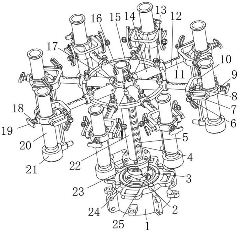
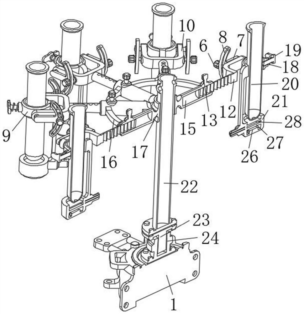
[0027] see Figure 1 to Figure 3 , the present invention provides a technical solution: a test tube placement rack for chemical experiments, including a base 1, a storage battery 3 is fixedly installed in the base 1 through bolts, and at least two independent batteries electrically connected to the storage battery 3 are fixedly installed on the base 1. Working button switch 2, the top of the base 1 is fixedly equipped with a lower mating seat 24 by bolts, and an upper mating seat 23 is installed above the lower mating seat 24 through a bearing, and the upper mating seat 23 is screwed and installed with a lower mating seat 24 Clamped matching seat positioning screw button 25;
[0028] The top of the upper mating seat 23 is fixed with a column 22 by bolts, and a guide protrusion 5 is integrally formed on the top of the column 22. The column 22 is sleeved with a sliding seat 17 that slides along the guide protrusion 5, and the sliding seat 17 At least four sleeves 14 are welded ...
Embodiment 2
[0035] see Figure 1 to Figure 4 , the present invention provides a technical solution: a test tube placement rack for chemical experiments, including a base 1, a storage battery 3 is fixedly installed in the base 1 through bolts, and at least two independent batteries electrically connected to the storage battery 3 are fixedly installed on the base 1. Working button switch 2, the top of the base 1 is fixedly equipped with a lower mating seat 24 by bolts, and an upper mating seat 23 is installed above the lower mating seat 24 through a bearing, and the upper mating seat 23 is screwed and installed with a lower mating seat 24 Clamped matching seat positioning screw button 25;
[0036] The top of the upper mating seat 23 is fixed with a column 22 by bolts, and a guide protrusion 5 is integrally formed on the top of the column 22. The column 22 is sleeved with a sliding seat 17 that slides along the guide protrusion 5, and the sliding seat 17 At least four sleeves 14 are welded ...
Embodiment 3
[0043] see figure 1 , figure 2 and Figure 5 , the present invention provides a technical solution: a test tube placement rack for chemical experiments, including a base 1, a storage battery 3 is fixedly installed in the base 1 through bolts, and at least two independent batteries electrically connected to the storage battery 3 are fixedly installed on the base 1. Working button switch 2, the top of the base 1 is fixedly equipped with a lower mating seat 24 by bolts, and an upper mating seat 23 is installed above the lower mating seat 24 through a bearing, and the upper mating seat 23 is screwed and installed with a lower mating seat 24 Clamped matching seat positioning screw button 25;
[0044] The top of the upper mating seat 23 is fixed with a column 22 by bolts, and a guide protrusion 5 is integrally formed on the top of the column 22. The column 22 is sleeved with a sliding seat 17 that slides along the guide protrusion 5, and the sliding seat 17 At least four sleeves...
PUM
 Abstract
Description
Claims
Application Information
 - R&D Engineer
- R&D Manager
- IP Professional
- Industry Leading Data Capabilities
- Powerful AI technology
- Patent DNA Extraction
Browse by: Latest US Patents, China's latest patents, Technical Efficacy Thesaurus, Application Domain, Technology Topic, Popular Technical Reports.
© 2024 PatSnap. All rights reserved.Legal|Privacy policy|Modern Slavery Act Transparency Statement|Sitemap|About US| Contact US: help@patsnap.com