Eureka AIR delivers breakthrough ideas for toughest innovation challenges, trusted by R&D personnel around the world.

Pediatric clinical intelligent diagnosis and detection device

A technology of an intelligent diagnosis and detection device, applied in the field of children's diagnosis, can solve the problems of damage, inconvenient replacement, complicated installation and disassembly, etc., and achieves the effect of convenient use, reasonable structure, and inconvenient replacement.

Inactive Publication Date: 2019-04-16
李瑞华
View PDF6 Cites 10 Cited by
  • Summary
  • Abstract
  • Description
  • Claims
  • Application Information

AI Technical Summary

Problems solved by technology

[0002] Clinical diagnosis means that the doctor examines the patient's disease, and classifies and identifies the etiology and pathogenesis of the patient's disease, as a method and way to formulate a treatment plan. The first step in diagnosis is to collect medical history by asking the patient's subjective symptoms Data and medical history can play a directional role in diagnosis and can prompt clues to diagnosis. With the continuous development of society, children's attention is becoming more and more important. Children need to be diagnosed and tested if they have uncomfortable problems. However, the existing pediatric Intelligent diagnostic testing equipment is exposed to the outside, and needs to be corrected and repaired after long-term use. However, most of the testing equipment is fixed and installed by bolts, which is cumbersome to install and disassemble, and is not convenient for staff to replace. One side of the testing equipment may be damaged or sprinkled with liquid medicine required for testing during the placement and testing process, causing damage to the equipment. Therefore, a new type of pediatric clinical intelligent diagnostic testing device is needed to meet people's needs

Method used


Image

  • Pediatric clinical intelligent diagnosis and detection device
  • Pediatric clinical intelligent diagnosis and detection device
  • Pediatric clinical intelligent diagnosis and detection device

Examples


Embodiment Construction

[0022] The following will clearly and completely describe the technical solutions in the embodiments of the present invention with reference to the accompanying drawings in the embodiments of the present invention. Obviously, the described embodiments are only some, not all, embodiments of the present invention.

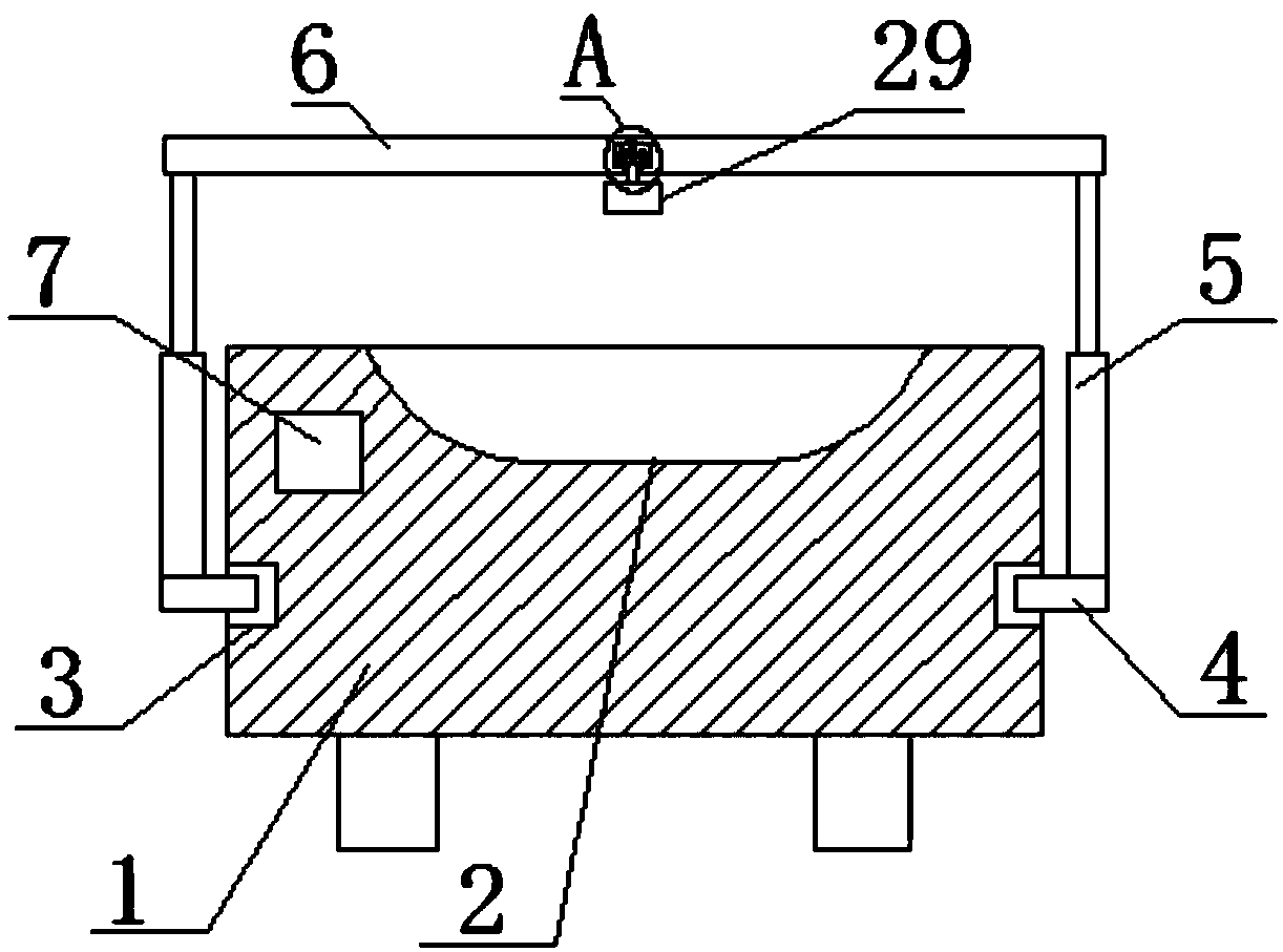
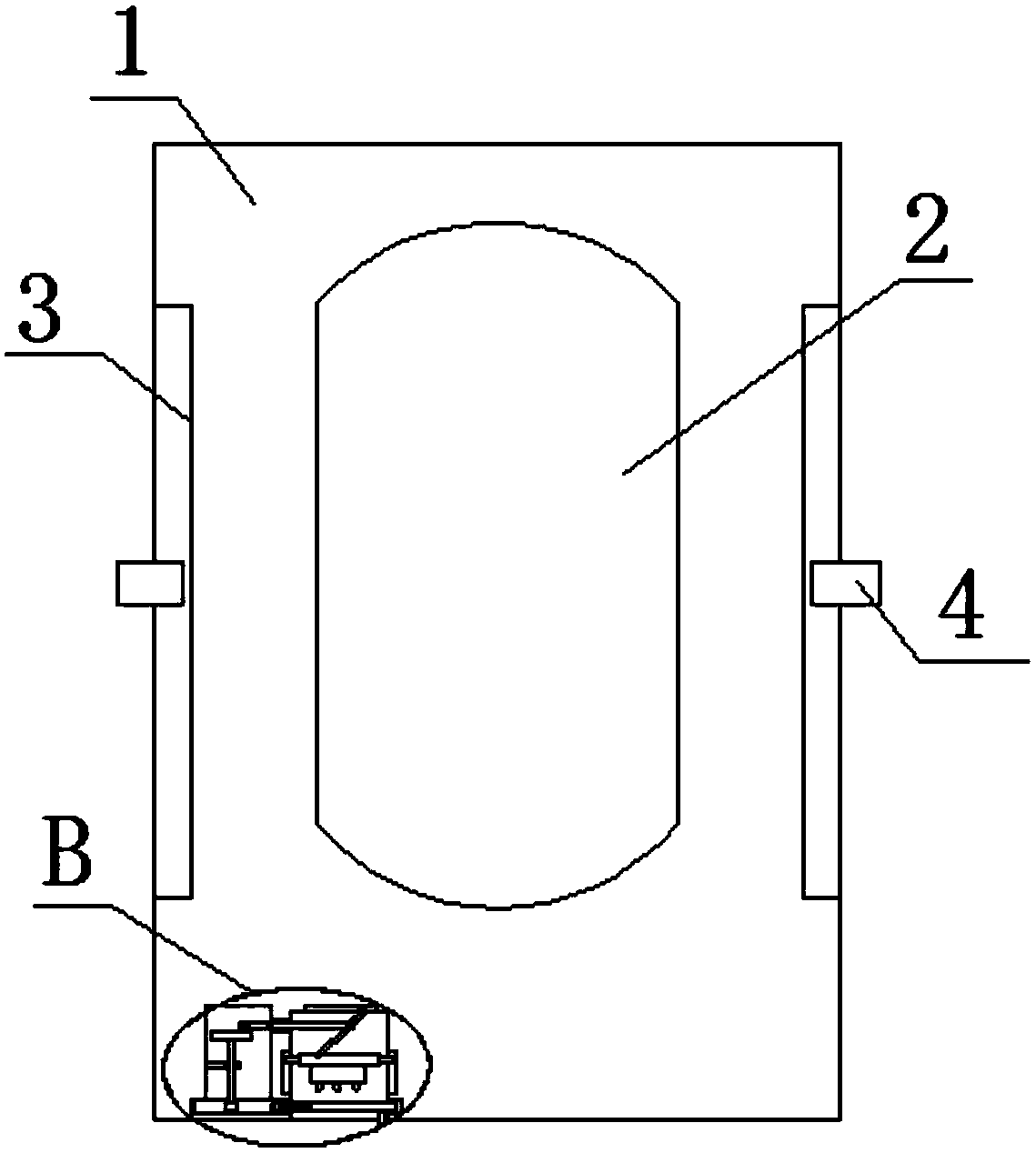
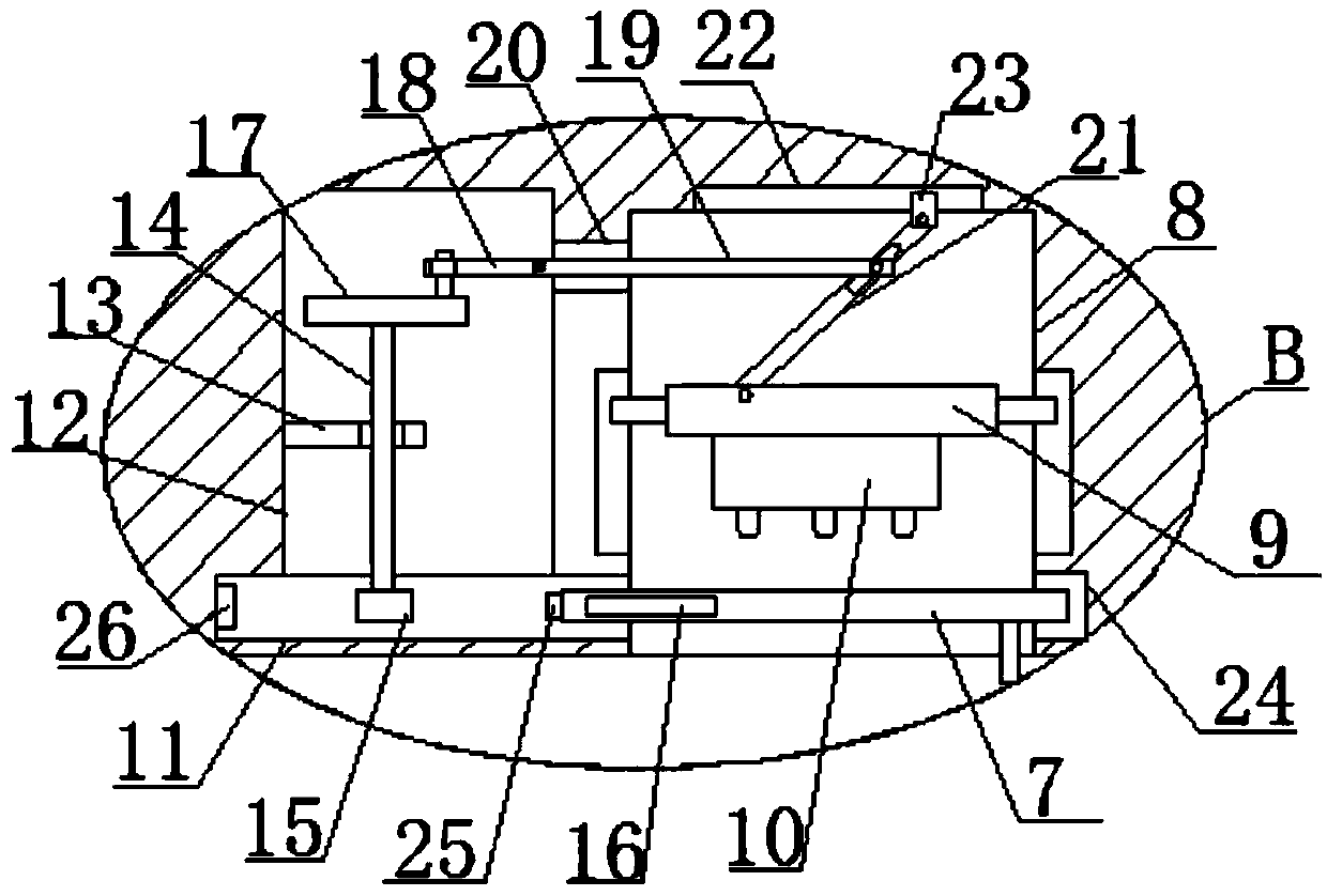
[0023] refer to Figure 1-5 , a pediatric clinical intelligent diagnosis and testing device, comprising a detection table 1, a lying groove 2 is provided on the top side of the detection table 1, an installation groove 8 is provided on one side of the detection table 1, and a mounting groove 8 is provided on one side of the installation groove 8. Door panel groove 11, a door panel 7 is installed movably in the door panel groove 11, one side of the door panel 7 extends into the installation groove 8, a placement plate 9 is movably installed in the installation groove 8, and a control switch 10 is provided on one side of the placement panel 9, the door panel A side inn...


PUM


Abstract

The invention discloses a pediatric clinical intelligent diagnosis and detection device comprising a detection platform. The top side of the detection platform is provided with a lying groove, a mounting groove is opened in one side of the detection platform, a door panel groove is opened in the inner wall on one side of the mounting groove, a door panel is movably mounted in the door panel groove, one side of the door panel extends into the mounting groove, and a placing plate is movably mounted in the mounting groove. The diagnosis and detection device is reasonable in structure. The door panel is opened to move to drive a gear to rotate to further drive an extrusion rod to move to drive a control switch to extend out of the mounting groove for use. The control switch extends into the mounting groove when not used. The problem that the control switch is easy to damage on the outside is effectively solved. At the same time, when an infrared thermometer is installed, fixed feet are moved to extrude a pressing plate to move to drive a V-shaped rod to rotate to driven a clamping rod to extend into a clamping rod groove, the problem that the infrared thermometer is inconvenient to replace is effectively solved, and the diagnosis and detection device is convenient to use.

Description

technical field [0001] The invention relates to the technical field of children's diagnosis, in particular to a pediatric clinical intelligent diagnosis and detection device. Background technique [0002] Clinical diagnosis means that the doctor examines the disease of the patient, and classifies and distinguishes the etiology and pathogenesis of the patient's disease, which is used as a method and way to formulate a treatment plan. The first step in diagnosis is to collect medical history by asking the patient's subjective symptoms Data and medical history can play a directional role in diagnosis and can prompt clues to diagnosis. With the continuous development of society, children's attention is becoming more and more important. Children need to be diagnosed when they have uncomfortable problems. However, the existing pediatric The intelligent diagnostic testing equipment is exposed to the outside, and needs to be corrected and repaired after long-term use. However, most ...

Claims


Application Information

Patent Timeline
IPC IPC(8): A61G13/00A61G13/10
CPCA61G13/0018A61G13/10A61G2200/14
Inventor 李瑞华
Owner 李瑞华
Why Eureka
Eureka Blog
Learn More