Trailer with storable tires
A technology for trailers and tires, which is applied in the field of trailers and can solve problems such as potential safety hazards and wheel rotation
- Summary
- Abstract
- Description
- Claims
- Application Information
AI Technical Summary
Problems solved by technology
Method used
Image
Examples
Embodiment 1
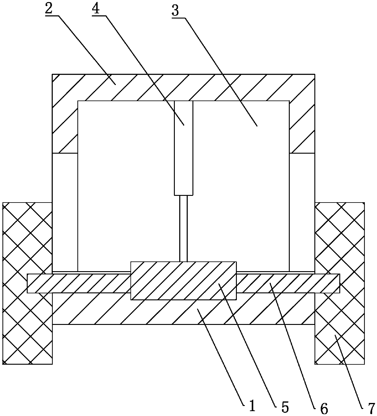
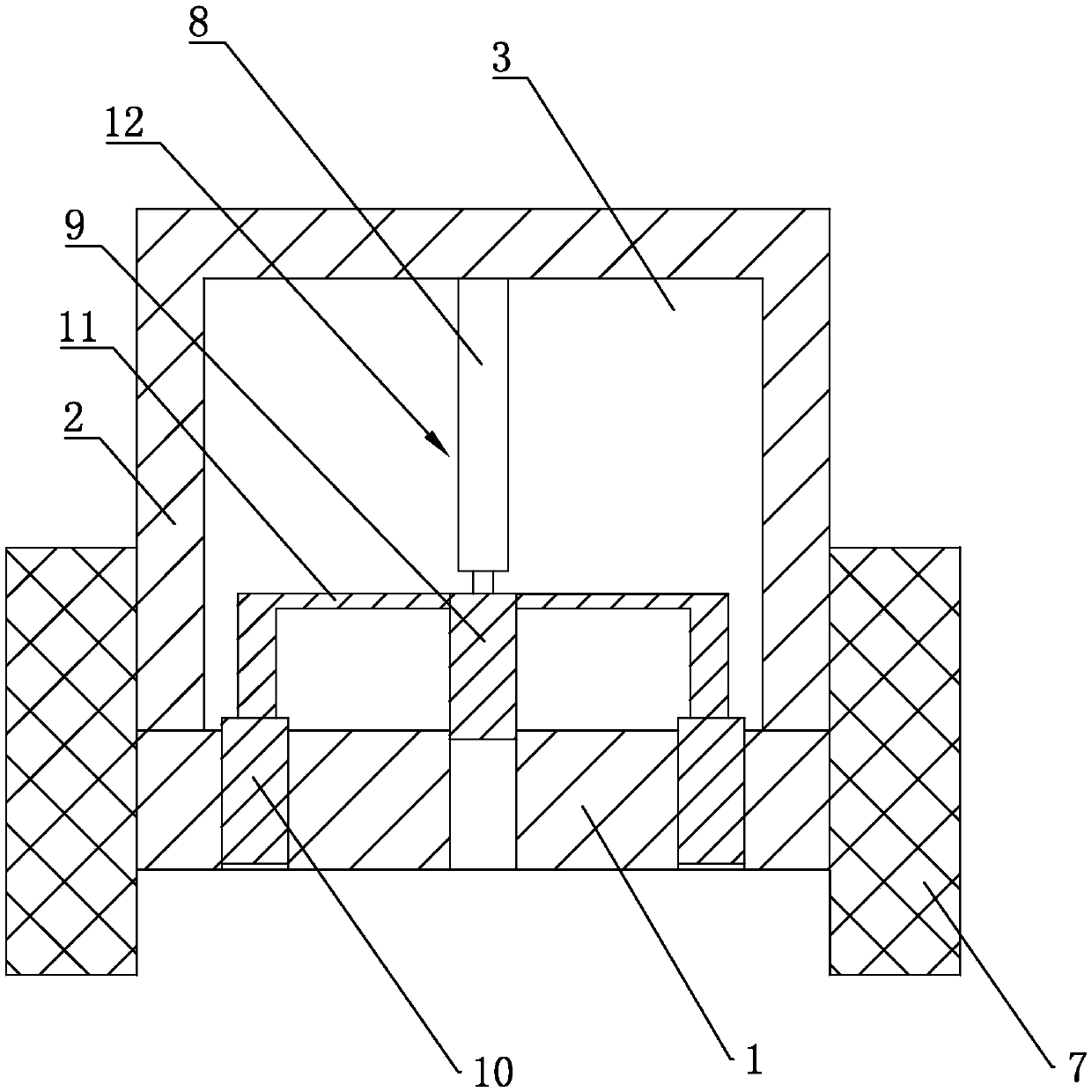
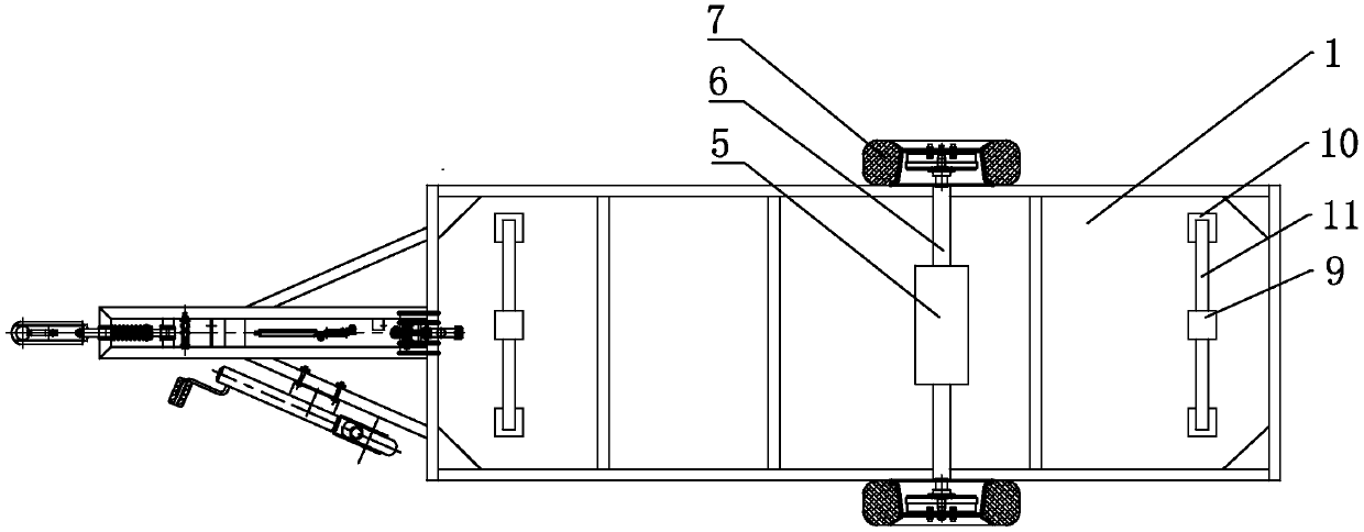
[0046] Such as figure 1 As shown, a tire-receivable trailer includes a base 1 and a placement platform 2 for placing materials. An accommodating space 3 is formed between the placing platform 2 and the base platform 1 . A first driving cylinder 4 is arranged vertically on the lower end surface of the placing table 2 , and a mounting block 5 is fixedly connected to the piston rod of the first driving cylinder 4 . A mounting shaft 6 is fixedly pierced on the mounting block 5 . The installation shaft 6 passes through the placement platform 2 and is slidably connected to the placement platform 2 along the vertical direction. Both ends of the installation shaft 6 are rotatably connected with rollers 7 , and the rollers 7 are located on both sides of the abutment 1 . The installation block 5 can be driven to move in the vertical direction by the first drive cylinder 4, thereby driving the roller 7 to move in the vertical direction.
[0047] Such as figure 2 and image 3 As sh...
Embodiment 2
[0053] The difference between embodiment two and embodiment one is:
[0054] Such as Figure 4 As shown, the drive mechanism 12 includes a first drive shaft 13, a second drive shaft 14, a first drive motor 15 for driving the first drive shaft 13 to rotate, and a second drive motor 16 for driving the second drive shaft 14 to rotate . Such as Figure 4 and Figure 5 As shown, the first drive shaft 13 is arranged vertically and is rotatably connected to the placement platform 2 and the base platform 1 . The first driving motor 15 is fixedly installed on the placement platform 2 , and the output shaft of the first driving motor 15 is fixedly provided with a first driving bevel gear 17 . The outer fixed sleeve of the first drive shaft 13 is provided with a first driven bevel gear 18 , and the first driven bevel gear 18 meshes with the first driving bevel gear 17 . The first drive motor 15 can drive the first drive shaft 13 to rotate under the action of force transmission from ...
Embodiment 3
[0063] The difference between the third embodiment and the first embodiment is that the driving mechanism 12 is different. Such as Figure 12As shown, the driving mechanism 12 includes a first driving shaft 13 , a second driving shaft 14 and a first driving motor 15 for driving the first driving shaft 13 to rotate. The first driving shaft 13 is arranged vertically and is rotatably connected to the placement platform 2 and the base platform 1 . The first driving motor 15 is fixedly installed on the placement platform 2 , and the output shaft of the first driving motor 15 is fixedly provided with a first driving bevel gear 17 . The outer fixed sleeve of the first drive shaft 13 is provided with a first driven bevel gear 18 , and the first driven bevel gear 18 meshes with the first driving bevel gear 17 . The first drive motor 15 can drive the first drive shaft 13 to rotate under the action of force transmission from the first driving bevel gear 17 and the first driven bevel ge...
PUM
 Abstract
Description
Claims
Application Information
 - R&D
- Intellectual Property
- Life Sciences
- Materials
- Tech Scout
- Unparalleled Data Quality
- Higher Quality Content
- 60% Fewer Hallucinations
Browse by: Latest US Patents, China's latest patents, Technical Efficacy Thesaurus, Application Domain, Technology Topic, Popular Technical Reports.
© 2025 PatSnap. All rights reserved.Legal|Privacy policy|Modern Slavery Act Transparency Statement|Sitemap|About US| Contact US: help@patsnap.com


