
Rear suspension balance shaft support

A technology of balancing shaft support and rear suspension, applied in the direction of suspension, interconnection system, transportation and packaging, etc., can solve the problems of unreasonable structure, weak bearing capacity, weak torsional moment capacity, etc., and achieve unit mass Small, high strength and rigidity, full-featured effect

Pending Publication Date: 2019-04-12
SINO TRUK JINAN POWER
View PDF12 Cites 0 Cited by
  • Summary
  • Abstract
  • Description
  • Claims
  • Application Information

AI Technical Summary

Problems solved by technology

[0003] 1. The structure is unreasonable: it is generally an open structure, which is composed of main vertical plates and corresponding reinforcement ribs. Due to structural limitations, the bearing capacity per unit mass is weak, which leads to excessive mass and light weight of the supports used for large-tonnage heavy-duty vehicles Difference
The ability to resist bending moments is poor, and the overall open structure has a weak ability to withstand torsional moments. In order to increase its rigidity, the only way to increase the main vertical plate and ribs is to increase its weight;
[0004] 2. The product has a single function: the support currently in use, in addition to the support function, only has the function of the lower thrust rod support. In order to realize the installation of the upper thrust rod, a special upper thrust rod support needs to be designed, and the space utilization The rate is not high, which increases the quality of the whole system
Existing products generally only have mounting holes for the balance shaft housing, and a specially designed shaft needs to be installed when installing the balance shaft housing, which not only increases the number of system parts and increases the weight, but also adversely affects the accuracy of the assembly (each There are tolerances in the processing of parts, and the fewer parts in the same function system, the more reasonable the precision control is)

Method used


Image

  • Rear suspension balance shaft support
  • Rear suspension balance shaft support
  • Rear suspension balance shaft support

Examples


Embodiment Construction

[0025] Attached below Figure 1-5 Specific embodiments illustrate the present invention in further detail.

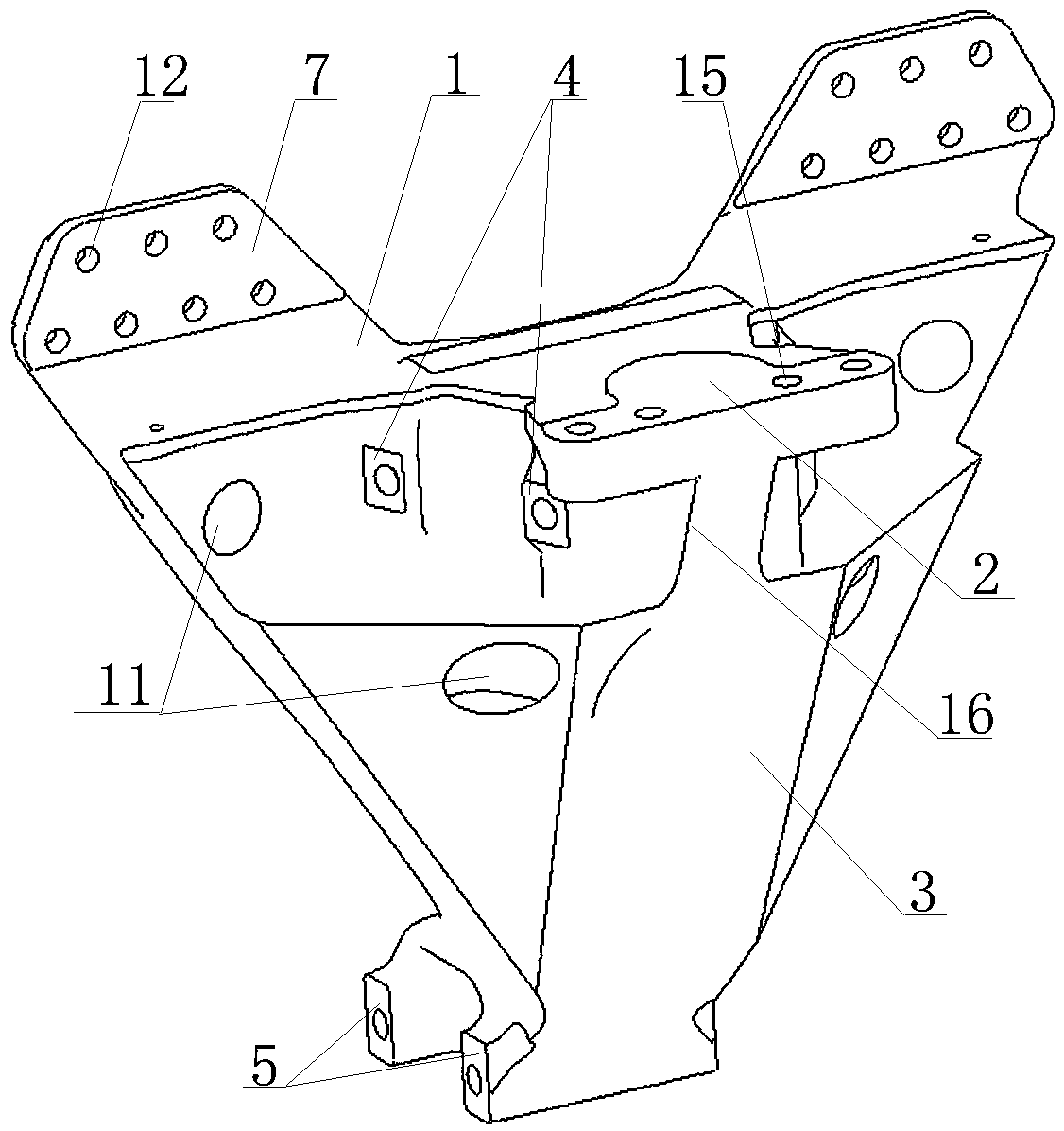
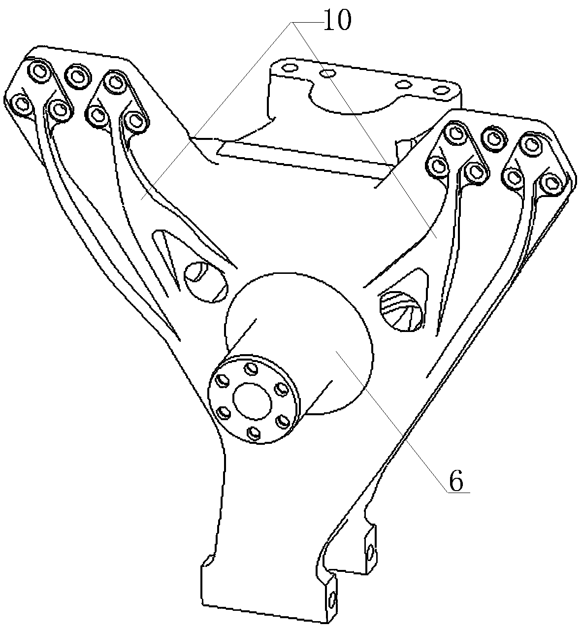
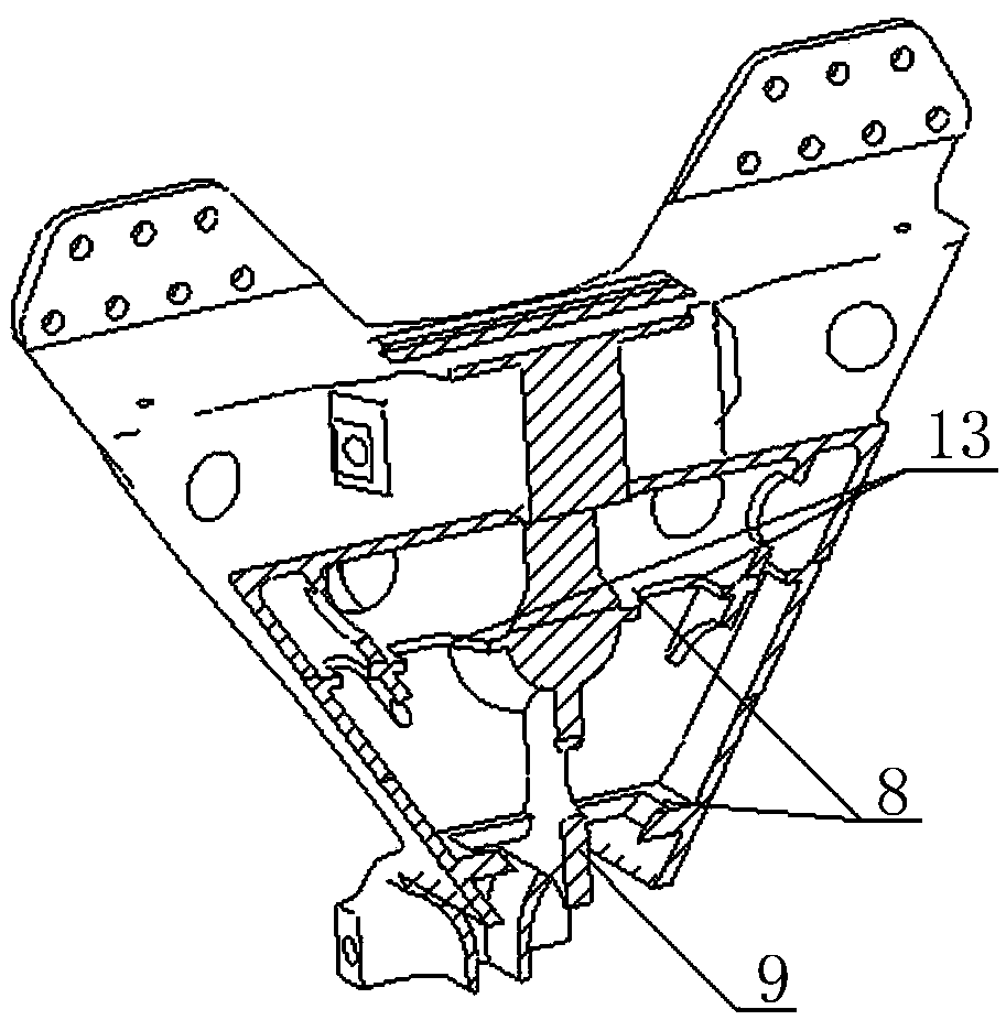
[0026] Such as Figure 1-5 The rear suspension balance shaft support shown mainly includes a plane base plate 1 distributed vertically in a flat plate structure, a beam mounting plate 2 perpendicular to the upper front side of the plane base plate 1, and a cavity forming a closed cavity structure with the plane base plate 1 body body 3.

[0027] Two support ears 7 are symmetrically connected to the left and right sides of the upper part of the plane base plate 1, and each support ear 7 is provided with a total of seven vehicle frame longitudinal beam mounting holes 12 distributed three times up and down four. 7 are provided with support ear reinforcing ribs 10, and the two support ears 7 are fixedly connected to the vehicle frame longitudinal beam by bolts.

[0028] The crossbeam mounting plate 2 is provided with a frame crossbeam mounting hole 15 for installation an...


PUM


Abstract

Aiming to solve the problems that a conventional balance shaft support is simple in function and unreasonable in structure, the invention provides a rear suspension balance shaft support. According tothe technical scheme, the rear suspension balance shaft support mainly comprises a planar base plate, a transverse beam mounting plate, a cavity main body, an upper propelling rod support and a lowerpropelling rod support, wherein the transverse beam mounting plate is vertically connected with the upper part of one side of the planar base plate; the cavity main body and the planar base plate form a sealed cavity; the upper propelling rod support is fixedly connected between the cavity main body and the transverse beam mounting plate; the lower propelling rod support is fixedly connected below the cavity main body and the planar base plate; the left end and the right end of the upper part of the planar base plate are fixedly connected with support lugs which are fixedly connected with a frame longitudinal beam; a plurality of frame longitudinal beam mounting holes are formed in the support lugs; the cavity main body and the transverse beam mounting plate are positioned on a same sideof the planar base plate; a balance shaft shell mounting shaft is fixedly connected with the other side of the planar base plate; the balance shaft shell mounting shaft is connected with the interiorof the cavity main body and extends into the cavity main body; both the upper propelling rod support and the lower propelling rod support are distributed in the length direction of the planar base plate.

Description

technical field [0001] The invention relates to the technical field of a balance shaft support of a heavy vehicle, in particular to a balance shaft support of a rear suspension. Background technique [0002] With the popularization of the integrated design concept of the automobile industry and the continuous upgrading of the consumption quality of heavy-duty truck products by customers, the requirements for multi-functional and easy-to-use products have been realized, and there are new requirements for innovative design of products. The balance shaft support currently in use mainly has the following disadvantages in terms of structure and function: [0003] 1. The structure is unreasonable: it is generally an open structure, which is composed of main vertical plates and corresponding reinforcement ribs. Due to structural limitations, the bearing capacity per unit mass is weak, which leads to excessive mass and light weight of the supports used for large-tonnage heavy-duty v...

Claims


Application Information

Patent Timeline
Patent Type & Authority Applications(China)
IPC IPC(8): B60G21/04
CPCB60G21/04
Inventor 霍崇亚秦磊王克奇冯聪张志刚李海林
Owner SINO TRUK JINAN POWER
Learn More