
Pipe baking device used for pipeline construction

A technology of pipeline construction and pipe bending device, applied in the field of pipeline processing, can solve the problems of poor quality, high price of hydraulic simmering and bending machine, difficult handling on construction site, etc.

Active Publication Date: 2019-04-12
嵊州市越通非开挖建设有限公司
View PDF7 Cites 2 Cited by
  • Summary
  • Abstract
  • Description
  • Claims
  • Application Information

AI Technical Summary

Problems solved by technology

[0002] In the construction of pipeline engineering, there are many occasions that require pipes with specific curvature to meet the construction requirements, which requires bending through straight pipes. At present, hydraulic pipe bending machines are mostly used for bending pipes, but hydraulic bending machines The price is expensive, and it is difficult to transport on the construction site. It also needs hydraulic drive. The most important thing is that the bending of the pipe bent by the hydraulic pipe bender is not uniform, which affects the construction quality.
[0003] The tube simmering machine is a machine that can heat the straight tube to the temperature of plastic deformation through intermediate frequency heating, and then restrict the straight tube to form a curved tube with a specified arc through the mechanical arm. The tube simmering machine currently used in the market can only be used to simmer 180 One-way bend within °, and the quality is not good, especially if the ellipse is too large, the accuracy is not accurate, and the use effect is not satisfactory. In addition, the equipment is expensive, and most pipeline installation units still use the traditional floor furnace for heating simmering tube method

Method used


Image

  • Pipe baking device used for pipeline construction
  • Pipe baking device used for pipeline construction
  • Pipe baking device used for pipeline construction

Examples


Embodiment Construction

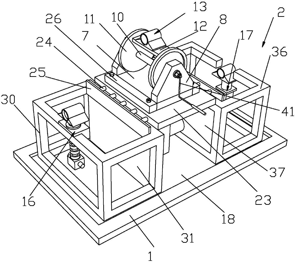
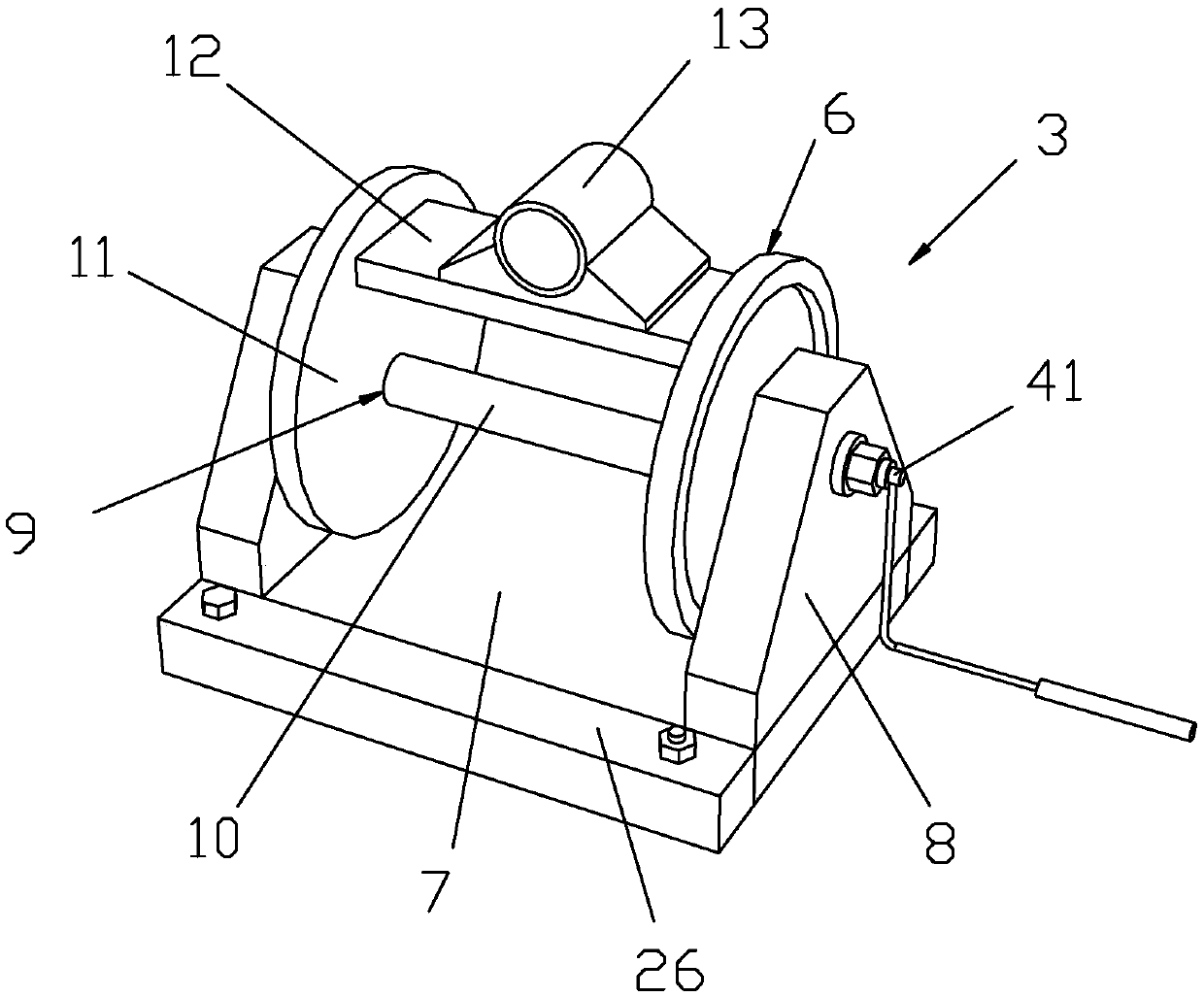
[0027] Such as Figure 1 to Figure 8 As shown, it is a pipe simmering device for pipeline construction of the present invention, including a workbench 1 and a simmering device 2, the simmering device 2 includes a pipe bending device 3 and a limiting device 4, and the pipe bending device 3 includes a mounting seat 5 and a bending device The tube bender 6, the tube bender 6 includes a bottom support plate 7, a lateral support plate 8 and a rotation mechanism 9, the rotation mechanism 9 includes a rotation shaft 10, a rotation disc 11 and a positioning plate 12, and the side support plate 8 is fixedly installed on the bottom support On both sides of the plate 7, a rotating shaft 10 is connected between the lateral support plates 8, and a rotating disc 11 is fixedly installed on both sides of the rotating shaft 10, and the rotating disc 11 is sleeved on the rotating shaft 10, and the rotating handle 41 passes through the lateral The support plate 8, the rotary handle 41 is arrange...


PUM


Abstract

The invention discloses a pipe baking device used for pipeline construction. The pipe baking device comprises a pipe bending device and a limiting device; the pipe bending device comprises an assemblybase and a pipe bender; the pipe bender comprises a bottom supporting plate, side supporting plates and a rotation mechanism; a rotary shaft is connected between the side supporting plates; rotary discs are fixedly arranged on two sides of the rotary shaft; the rotary discs sleeve the rotary shaft; one side of the rotary shaft is connected to a rotary handle; the rotary handle is arranged on theouter side of the corresponding side supporting plate; a positioning plate is arranged between the two rotary discs; a node component is arranged on the positioning plate; the limiting device comprises an upper limiting component and a lower limiting component; and an upward pipe bender is arranged on the upper limiting component. By adopting the pipe baking device, bending degrees with two opposite directions and different angles can be manufactured at the same time according to needs; and the pipe bending effect of long pipelines and short pipelines can be realized by adjusting the positionof the limiting device; the integral structure is more firm and stable.

Description

technical field [0001] The invention belongs to the technical field of pipeline processing, and in particular relates to a pipe stewing device for pipeline construction. Background technique [0002] In the construction of pipeline engineering, there are many occasions that require pipes with specific curvature to meet the construction requirements, which requires bending through straight pipes. At present, hydraulic pipe bending machines are mostly used for bending pipes, but hydraulic bending machines The price is expensive, and it is difficult to transport on the construction site, and hydraulic drive is required. The most critical thing is that the bending of the pipe bent by the hydraulic pipe bender is uneven, which affects the construction quality. [0003] The tube simmering machine is a machine that can heat the straight tube to the temperature of plastic deformation through intermediate frequency heating, and then restrict the straight tube to form a curved tube wi...

Claims


Application Information

Patent Timeline
Patent Type & Authority Applications(China)
IPC IPC(8): B21D7/16B21D7/14B21D7/00
CPCB21D7/00B21D7/14B21D7/16B21D7/162
Inventor 支黎锋
Owner 嵊州市越通非开挖建设有限公司
Learn More