A garden pond feed throwing equipment
A kind of feed equipment and feed technology, which is applied in application, climate change adaptation, fish farming, etc., can solve the problems of high cost and trouble of feed throwing and speculation, and achieve the effects of small footprint, save trouble, and prevent clogging
- Summary
- Abstract
- Description
- Claims
- Application Information
AI Technical Summary
Problems solved by technology
Method used
Image

Examples
Embodiment 1
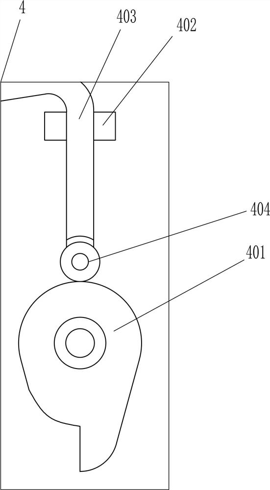
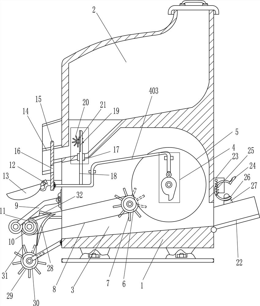
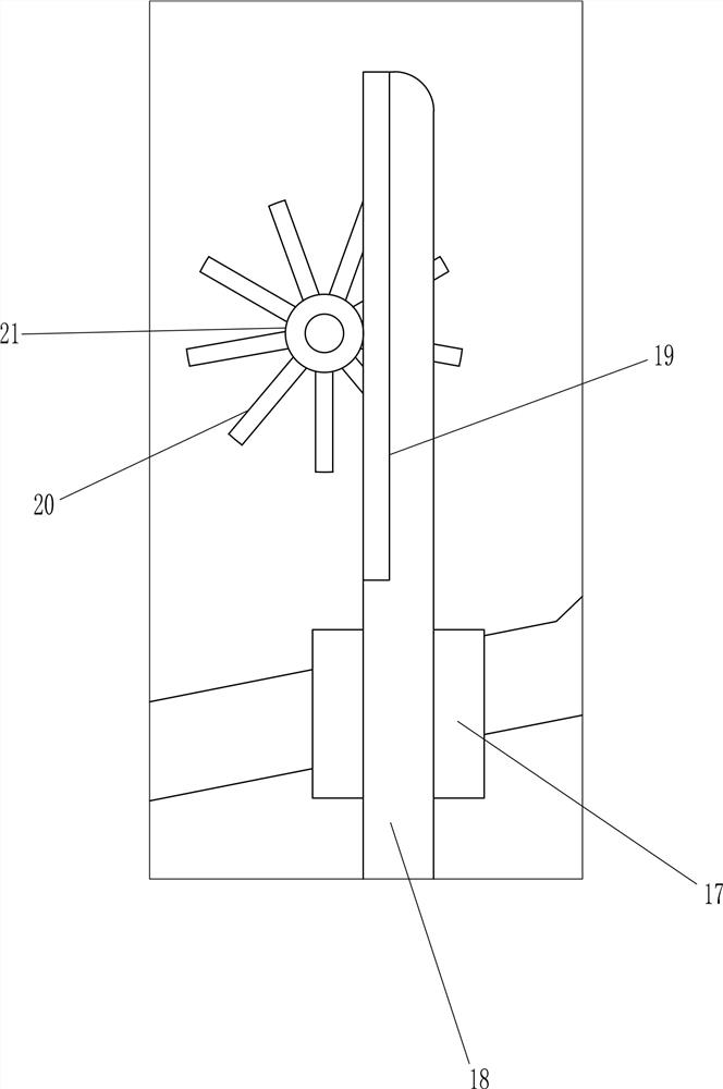
[0021] A garden pond throwing feed equipment, such as Figure 1-3 As shown, it includes a feed throwing box 1, a driving mechanism 4, a large gear 5, a pinion 6, a first water wheel 7, a first flat belt 8, a connecting rod 9, a first gear 10, a first pulley 11, and a mounting seat 12. Parabolic frame 13, discharge box 14, lifting plate 15 and knocking rod 32. Storage tank 2 is opened in the upper part of feed throwing box 1, and water filter tank 3 is opened in the lower part of feed throwing box 1. The front wall of filter water tank 3 is on the right side. The side is provided with a drive mechanism 4, and a large gear 5 is installed on the parts of the drive mechanism 4. The first water wheel 7 is rotatably installed on the lower part of the inner rear wall of the filter tank 3, and the lower part of the left side of the feed throwing box 1 is connected with a connecting rod 9. The left end of the rod 9 and the left side of the bottom are all rotatably equipped with a first...
Embodiment 2
[0023] A garden pond throwing feed equipment, such as Figure 1-3 As shown, it includes a feed throwing box 1, a driving mechanism 4, a large gear 5, a pinion 6, a first water wheel 7, a first flat belt 8, a connecting rod 9, a first gear 10, a first pulley 11, and a mounting seat 12. Parabolic frame 13, discharge box 14, lifting plate 15 and knocking rod 32. Storage tank 2 is opened in the upper part of feed throwing box 1, and water filter tank 3 is opened in the lower part of feed throwing box 1. The front wall of filter water tank 3 is on the right side. The side is provided with a drive mechanism 4, and a large gear 5 is installed on the parts of the drive mechanism 4. The first water wheel 7 is rotatably installed on the lower part of the inner rear wall of the filter tank 3, and the lower part of the left side of the feed throwing box 1 is connected with a connecting rod 9. The left end of the rod 9 and the left side of the bottom are all rotatably equipped with a first...
Embodiment 3
[0026] A garden pond throwing feed equipment, such as Figure 1-3 As shown, it includes a feed throwing box 1, a driving mechanism 4, a large gear 5, a pinion 6, a first water wheel 7, a first flat belt 8, a connecting rod 9, a first gear 10, a first pulley 11, and a mounting seat 12. Parabolic frame 13, discharge box 14, lifting plate 15 and knocking rod 32. Storage tank 2 is opened in the upper part of feed throwing box 1, and water filter tank 3 is opened in the lower part of feed throwing box 1. The front wall of filter water tank 3 is on the right side. The side is provided with a drive mechanism 4, and a large gear 5 is installed on the parts of the drive mechanism 4. The first water wheel 7 is rotatably installed on the lower part of the inner rear wall of the filter tank 3, and the lower part of the left side of the feed throwing box 1 is connected with a connecting rod 9. The left end of the rod 9 and the left side of the bottom are all rotatably equipped with a first...
PUM
 Abstract
Description
Claims
Application Information
 - Generate Ideas
- Intellectual Property
- Life Sciences
- Materials
- Tech Scout
- Unparalleled Data Quality
- Higher Quality Content
- 60% Fewer Hallucinations
Browse by: Latest US Patents, China's latest patents, Technical Efficacy Thesaurus, Application Domain, Technology Topic, Popular Technical Reports.
© 2025 PatSnap. All rights reserved.Legal|Privacy policy|Modern Slavery Act Transparency Statement|Sitemap|About US| Contact US: help@patsnap.com