
Positioning device with flexible structure and positioning method of positioning device

A positioning device and flexible structure technology, applied in the direction of positioning device, clamping, support, etc., can solve the problems of low precision, large surface area of ​​finishing, low service life, etc., and achieve the effect of precise positioning

Active Publication Date: 2019-04-09
BEIJING INST OF AEROSPACE CONTROL DEVICES
View PDF7 Cites 0 Cited by
  • Summary
  • Abstract
  • Description
  • Claims
  • Application Information

AI Technical Summary

Problems solved by technology

[0002] If the devices in the prior art need to be positioned in two directions at the same time, it is necessary to combine two or more connecting devices to use together, and the installation requirements of the combined devices are high
And it is only suitable for medium and large parts with low precision. Secondly, because the above positioning is rigid positioning, the clamping pin and the center hole wear a lot, and the service life is low
There are also disadvantages in the prior art that the finishing surface area is relatively large, the processing is difficult and the cost is high, and the avoidance groove will generate stress concentration when deformed, which will affect the service life
[0003] In summary, the disadvantages of the existing devices are that the finished surface area is large and the processing is difficult; when the tensioning device is working, it will easily cause wear or stress concentration during the simultaneous positioning and assembly process, which will affect the service life of the pallet

Method used


Image

  • Positioning device with flexible structure and positioning method of positioning device
  • Positioning device with flexible structure and positioning method of positioning device
  • Positioning device with flexible structure and positioning method of positioning device

Examples


Embodiment Construction

[0032] The present invention will be further described in detail below in conjunction with the accompanying drawings and specific embodiments.

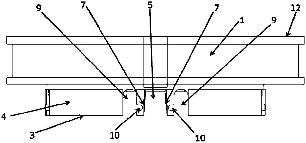
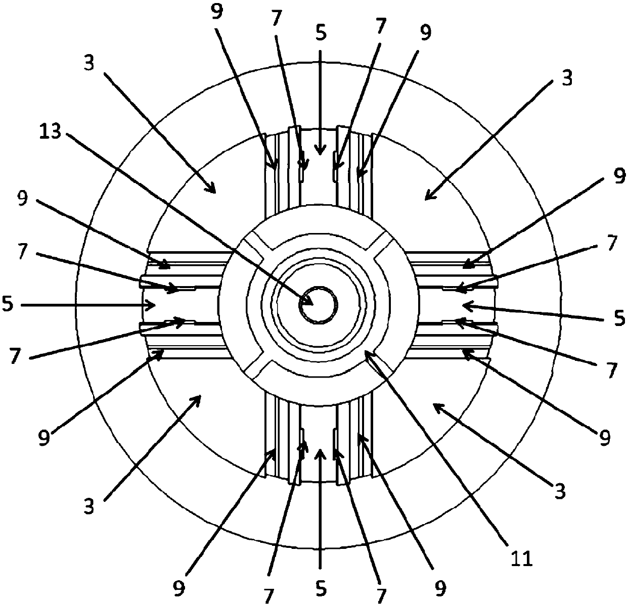
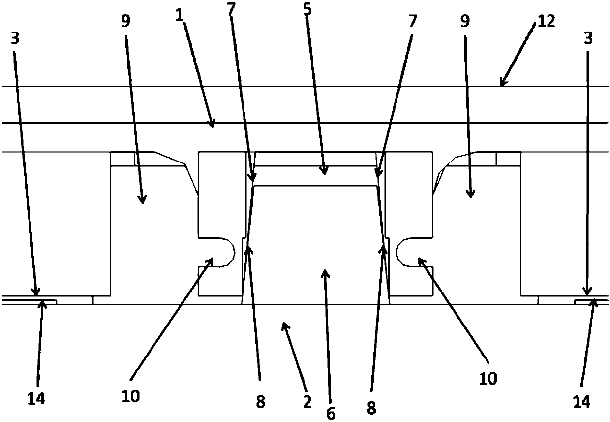
[0033] The present invention is a positioning device with a flexible structure and a positioning method thereof. The positioning device with a flexible structure is placed on a chuck; the positioning device with a flexible structure passes the groove edge of the positioning groove 5 and the positioning slope of the positioning tooth Contact; there is a small gap between the Z-direction positioning surface 3 of the positioning device with a flexible structure and the Z-direction positioning surface of the chuck; a threaded through hole is opened in the middle of the positioning device with a flexible structure, and a puller is installed on the threaded through hole. Tighten the nail with a tensioning device, and the positioning device moves toward the chuck until the Z-direction positioning surface of the chuck closely fits with the Z-d...


PUM


Abstract

The invention discloses a positioning device with a flexible structure and a positioning method of the positioning device. The positioning device with the flexible structure is placed on a clamping disc, the positioning device with the flexible structure is in contact with the positioning bevel of a positioning tooth through the groove edge of a positioning groove 5, and a small gap is kept between the Z positioning surface 3 of the positioning device with the flexible structure and the Z positioning surface of the clamping disc; and a threaded through hole is formed in the middle of the positioning device with the flexible structure, a pull nail is mounted in the threaded through hole, a tensioning device is used to pull the nail, the positioning device moves towards the direction of theclamping disc until the Z positioning surface of the clamping disc is closely attached to the Z positioning surface 3 of the positioning device with the flexible structure, a U-shaped notch 10 is deformed in the moving process of the direction of the groove bottom of the positioning groove 5 of the positioning device with the flexible structure to the positioning tooth, the opening in the bottom of the positioning groove is expanded, the part below the U-shaped 10 notch on the positioning bevel of the positioning groove 5 is closely fitted with the positioning bevel of the positioning teeth, and the positioning teeth are clamped. The high precision positioning of the positioning device with the flexible structure and the clamping disc is realized.

Description

technical field [0001] The invention relates to the technical field of positioning and clamping between a machine tool and a workpiece in precision machinery manufacturing, in particular to a positioning device with a flexible structure and a positioning method thereof. Background technique [0002] If the devices in the prior art need to be positioned in two directions at the same time, it is necessary to combine two or more connecting devices for use together, and the installation requirements of the combined devices are high. And it is only suitable for medium and large parts with low precision. Secondly, because the above-mentioned positioning is a rigid positioning, the clamping pin and the center hole wear a lot, and the service life is low. There are also disadvantages in the prior art that the area of ​​the finished surface is large, the processing is difficult and the cost is high, and the stress concentration will be generated when the avoidance groove is deformed,...

Claims


Application Information

Patent Timeline
Patent Type & Authority Applications(China)
IPC IPC(8): B23Q3/06
CPCB23Q3/06
Inventor 王锐胡玉龙刘宇轩于得涛严小军温鹏飞刘兴
Owner BEIJING INST OF AEROSPACE CONTROL DEVICES
Learn More