


Quick Research
Generate reliable direction feasibility study reports for your R&D in just a few steps.

Technical Q&A
Discover and master advanced knowledge NOW. Basics, ideas, possibilities, all at once.

Find Solutions
As an expert in R&D theories, this can generate solutions to your technical problems instantly.

Evaluate Feasibility
Analyze your overall solution with one click, know your potential R&D risks in advance.

Monitor Landscape
Get weekly tech updates, stay abreast of the latest tech innovations and key insights.
Vibrating liver forceps
A technique of liver clamp and vibrating mode is applied in the field of vibrating liver clamp to achieve the effects of alleviating the pain of the patient, improving the work efficiency, and having a large working area.
- Summary
- Abstract
- Description
- Claims
- Application Information
AI Technical Summary
Problems solved by technology
Method used
Image

Examples
Embodiment 1
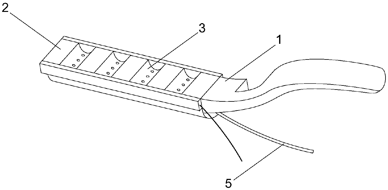
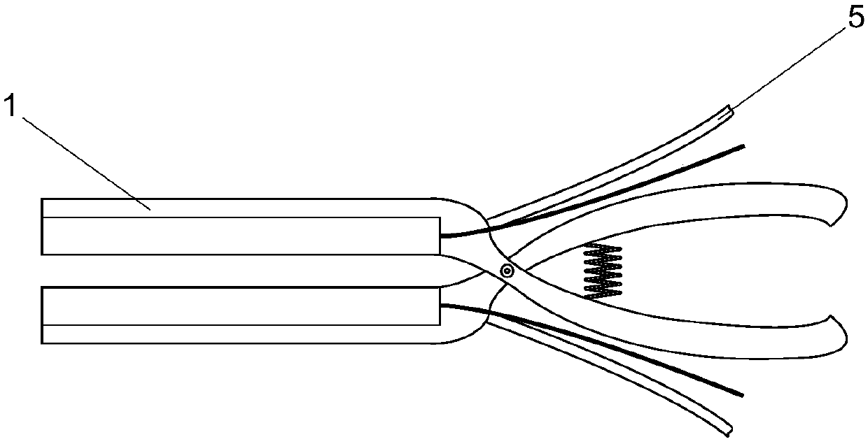
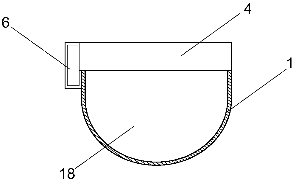
[0026] like Figure 1 to Figure 4 As shown, a vibrating liver forceps includes a pair of hinged forceps body 1, five vibration modules 2 and four absorption grooves 3 are arranged on the clamping surface of the forceps body 1, and the vibration modules 2 and the absorption grooves 3 are spaced apart distributed. The vibration module 2 includes a vibration module box body 4, a vibration device and a vibration body 20, the vibration device is connected with the vibration body 20, the vibration device is connected with an external controller, and the absorption tank 3 is communicated with a negative pressure air source. In the embodiment, the negative pressure air source is the vacuum port of the ward. The forceps body 1 includes a clamping section and an operating section, the hinge of the forceps body 1 is located between the clamping section and the operating section, the cross section of the clamping section is U-shaped, and the U-shaped cavity of the clamping section forms ...
Embodiment 2
[0029] like Figure 5 to Figure 8 As shown, the vibration module box body 4 is a cuboid with a top cover. There are four vibration modules 2 and five absorption grooves 3 . Each vibrating body 20 includes a top plate and a sliding column, the top plate and the sliding column are integrally formed, the top plate is located outside the top cover of the vibration module box body 4, and the sliding column is slidably inserted in the center hole of the vibration module box body 4 top cover and is connected to the vibration module box body 4. The walls of the central bore remain in sealing contact. Described vibrating device comprises gas control gear 11 and extension spring 7, and vibrating body 20 bottom surface is connected with vibrating module box body 4 by extension spring 7, and the top plate of vibrating body 20 exceeds vibrating module box body 4 sides, and is connected with caliper body 1. The central axis is vertical to form a protruding lip 8. A rack 9 is fixed on the ...
Embodiment 3
[0032] There are six vibration modules 2, and seven absorption grooves 3. All the other are with embodiment 1.
PUM
 Abstract
Description
Claims
Application Information
 - R&D Engineer
- R&D Manager
- IP Professional
- Industry Leading Data Capabilities
- Powerful AI technology
- Patent DNA Extraction
Browse by: Latest US Patents, China's latest patents, Technical Efficacy Thesaurus, Application Domain, Technology Topic, Popular Technical Reports.
© 2024 PatSnap. All rights reserved.Legal|Privacy policy|Modern Slavery Act Transparency Statement|Sitemap|About US| Contact US: help@patsnap.com