
A mounting device for connector pins

A technology for installing equipment and connectors, which is applied in the assembly/disassembly of contacts, metal processing equipment, and contact manufacturing. The effect of improving production efficiency

Active Publication Date: 2020-06-30
浙江勇创自动化科技有限公司
View PDF3 Cites 0 Cited by
  • Summary
  • Abstract
  • Description
  • Claims
  • Application Information

AI Technical Summary

Problems solved by technology

The production of conductive pins is generally formed by stamping the metal strip through punching machines and other equipment to form a structure in which one end is fixed on the conductive pin strip, and then when it is necessary to install multiple conductive pins on the insulating seat, special equipment is required. To increase the production speed, otherwise, when artificially plugged and installed, the production efficiency will be directly reduced due to the excessive number of parts, which will increase the labor cost and reduce the production efficiency.

Method used


Image

  • A mounting device for connector pins
  • A mounting device for connector pins
  • A mounting device for connector pins

Examples


Embodiment Construction

[0044] The present invention will be described in further detail below in conjunction with the accompanying drawings.

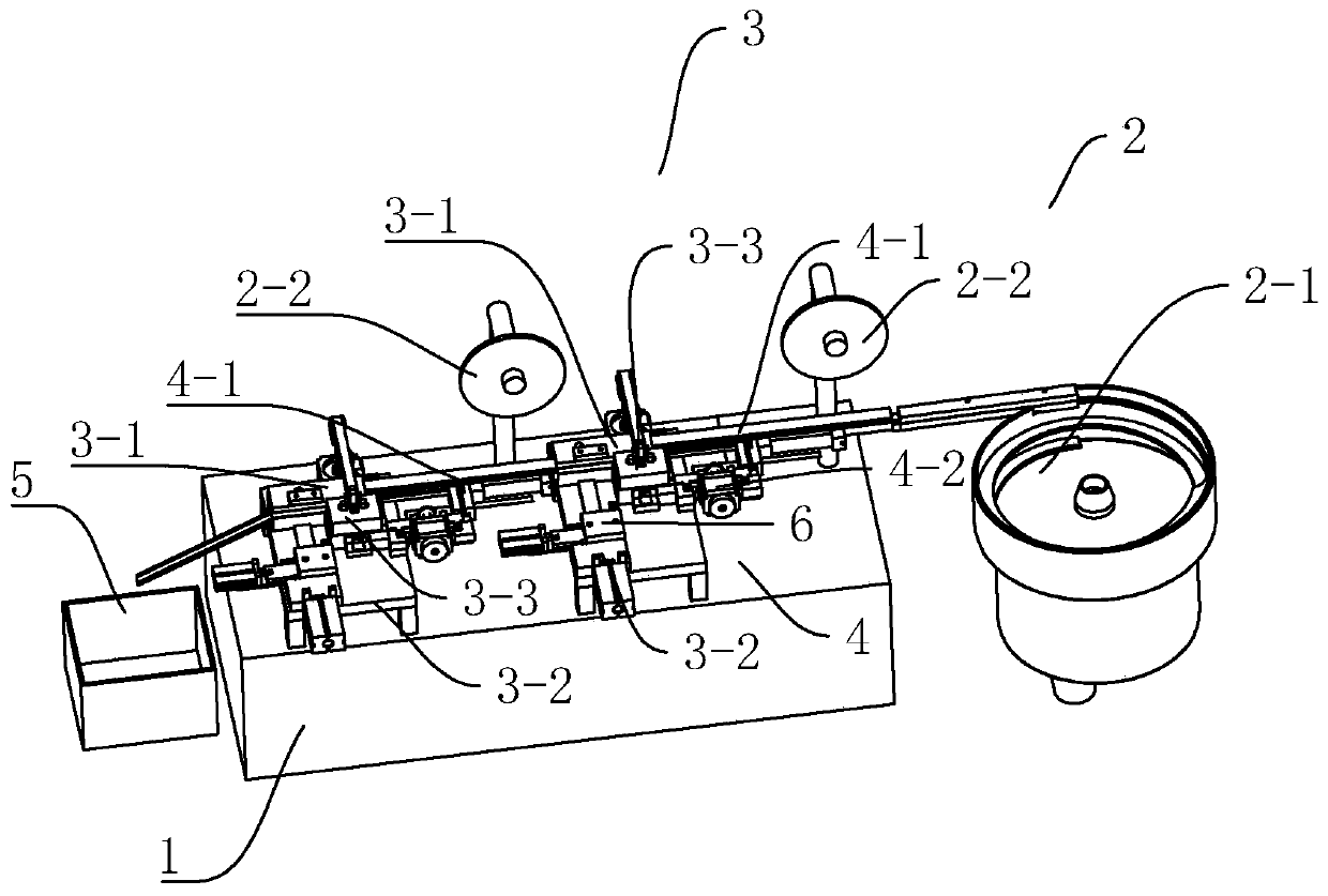
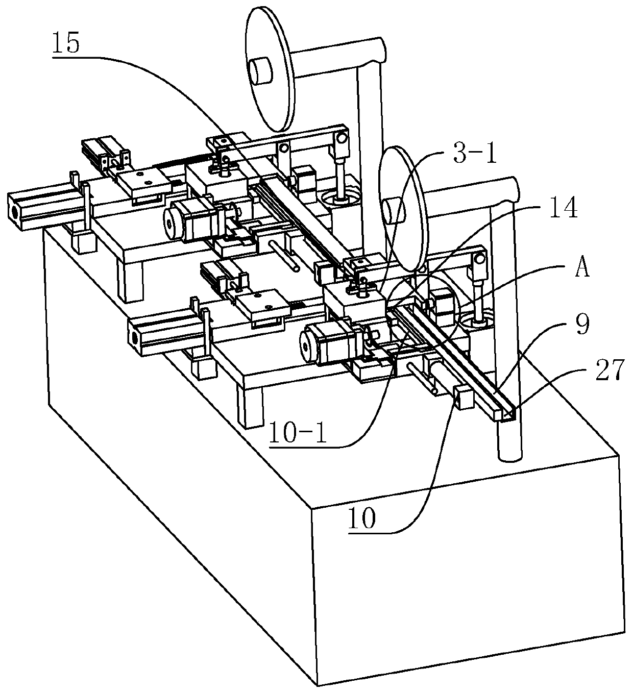
[0045] A mounting device for connector pins, ref. figure 2 , including a workbench 1, a feeding mechanism 2, an installation mechanism 3, a feeding mechanism 4 and a collecting mechanism 5. On the workbench 1, there are first feeding part 2-1, first feeding table 4-1, installation table 3-1, and second feeding part 2 located above the installation table 3-1 in order from left to right. -2. The fixed seat 3-3 and the transfer assembly 3-2 located on the side of the installation platform 3-1, the first material conveying platform 4-1, the installation platform 3-1, and the second feeder located above the installation platform 3-1 The material section 2-2, the fixed seat 3-3 located on one side of the installation table 3-1, and the transfer assembly 3-2 are used as the receiving seat of the collecting mechanism 5. There are two sets of multiple components, a...


PUM


Abstract

The invention discloses a mounting device for a connector pin, and is characterized in that the mounting device for the connector pin includes a working table, wherein a feeding mechanism is arrangedon the working table; a mounting mechanism; a feeding mechanism; and a collection mechanism; a transfer component includes a connecting seat for transferring a conducting pin, a longitudinal driving cylinder group for driving the connecting seat to move towards fixed points which are a fixing seat and a mounting platform, and a transverse driving cylinder group locating on the longitudinal drivingcylinder group and used for driving the connecting seat to move towards the fixing seat. The invention has the following advantage and effect: the conducting pin is transferred to a fixed point by the transfer component, and an insulating base is placed at a fixed point to realize the continuous mounting of the conducting pin and the insulating base.

Description

technical field [0001] The invention relates to PCB connector installation equipment, in particular to a installation equipment for connector pins. Background technique [0002] The electrical connector is composed of an insulating base body and many conductive pins. Conductive pins must be properly combined and fixed to ensure the quality of the connection during use. [0003] For example Figure 8 , Figure 9 The shown connector 28 includes an insulating base body and eight conductive pins, four in each row and two rows are fixed on the insulating base body. The production of conductive pins is generally formed by stamping the metal strip through punching machines and other equipment to form a structure in which one end is fixed on the conductive pin strip, and then when it is necessary to install multiple conductive pins on the insulating seat, special equipment is required. Proper production is used to increase the production speed. Otherwise, when artificially plugge...

Claims


Application Information

Patent Timeline
Patent Type & Authority Patents(China)
IPC IPC(8): H01R43/20H01R43/16B23P19/00
CPCB23P19/001B23P19/004H01R43/16H01R43/20
Inventor 许辉冀
Owner 浙江勇创自动化科技有限公司
Learn More