Clutch for fracturing device and control method
A clutch and input device technology, applied in the direction of clutches, fluid-driven clutches, non-mechanical drive clutches, etc., can solve the problems of long pressure oil transmission path, pressure oil leakage, safety accidents, etc., to reduce equipment losses, avoid loss expansion, The effect of improving reliability
- Summary
- Abstract
- Description
- Claims
- Application Information
AI Technical Summary
Problems solved by technology
Method used
Image
Examples
Embodiment 1
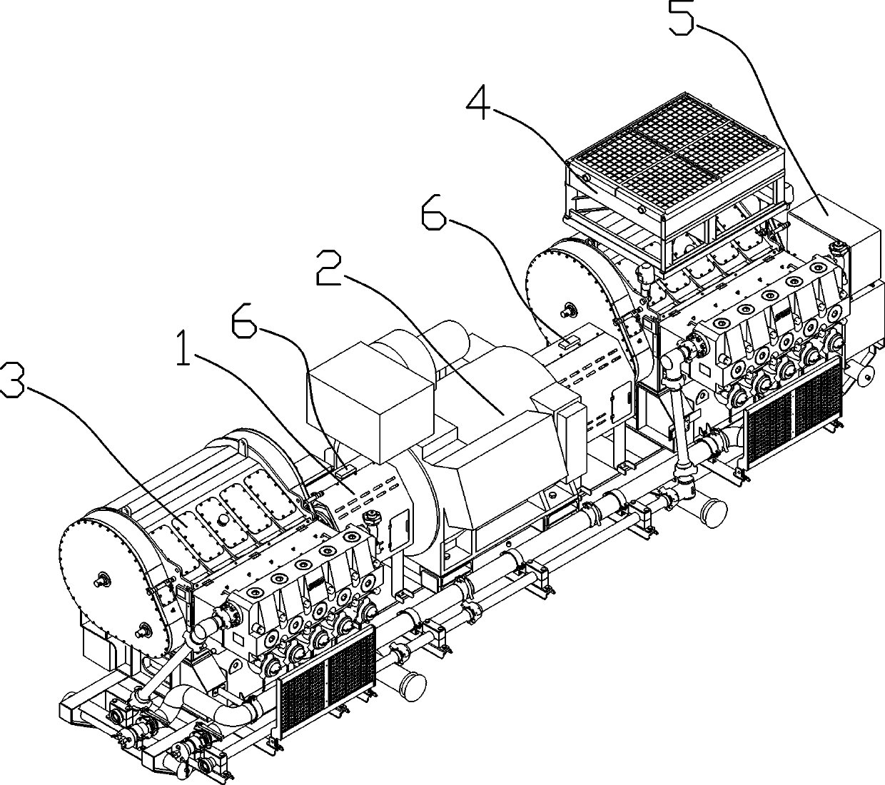
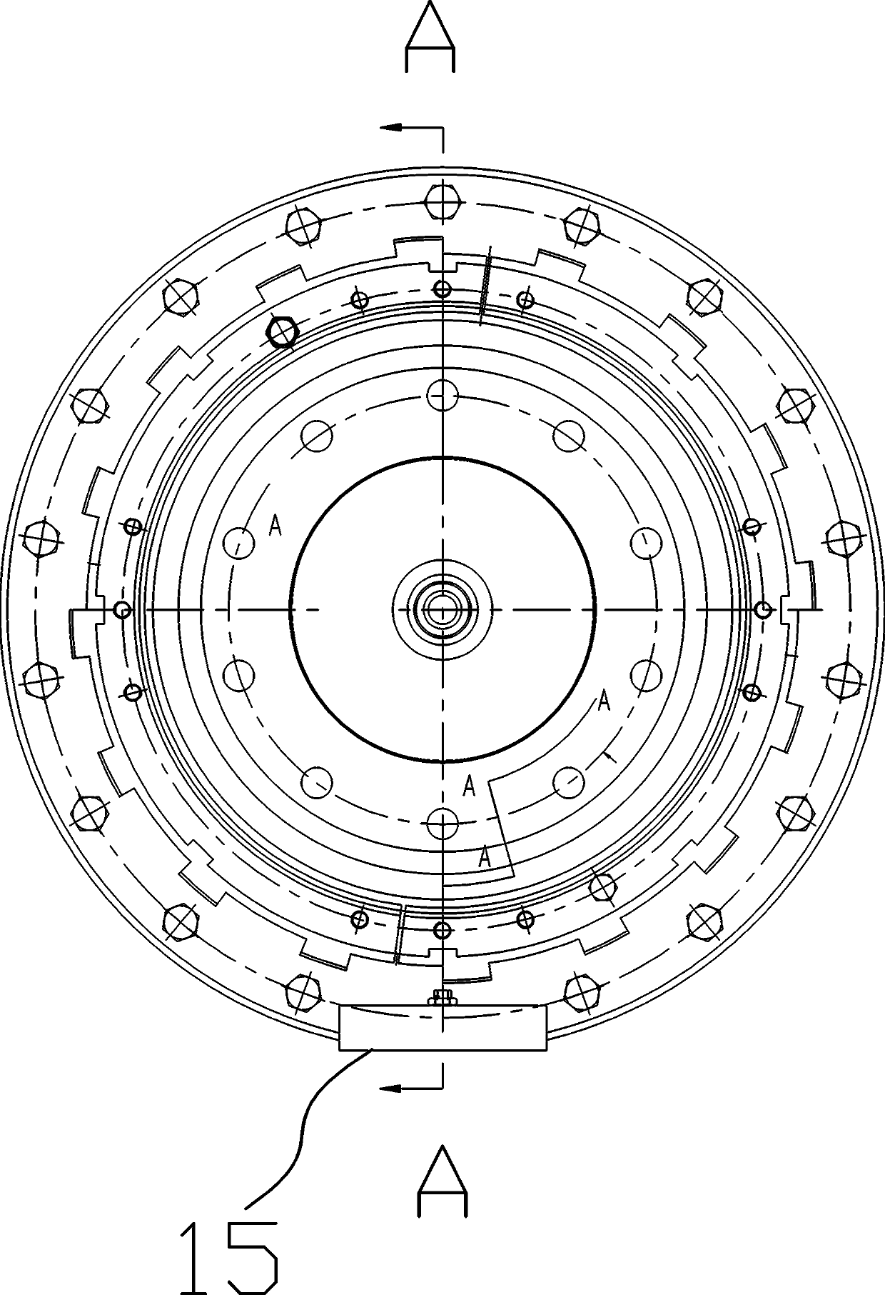
[0040] Such as Figure 2~4 Among them, a clutch for a fracturing device, which includes a pump connection part 11, a transmission part 12 and a motor connection part 13, and the pump connection part 11 and the transmission part 12 are connected in a clutchable manner through a friction plate assembly 18 , the transmission part 12 is connected with the motor connection part 13; the friction plate assembly 18 is a prior art, including a piston, a plurality of friction plates and a plurality of pressure plates for friction transmission, and is also provided with a mechanism for resetting the pressure plate The spring realizes the clutch transmission through the axial movement of a plurality of pressure plates, which are all prior art, such as the structure recorded in a tractor wet friction clutch described in the patent document CN201820235004.1, Figure 7 A schematic structural diagram of the friction plate assembly 18 is shown in , which will not be repeated here.
[0041] Th...
Embodiment 2
[0059] On the basis of Embodiment 1, a control method using the above-mentioned clutch for a fracturing device includes the following steps:
[0060] S1. When the controller issues a command, such as a PLC command, the solenoid valve 7 of the hydraulic oil circuit of the clutch 1 is turned on, and the hydraulic oil enters the oil inlet hole 111 of the clutch 1, and passes through the rotation speed of the motor 2 and the central axis of the pump head assembly 3. The speed difference between the rotating speeds judges whether the clutch 1 is engaged; at this time, after a period of time, the rotating speed of the motor 2 should be the same as the rotating speed of the central axis of the pump head assembly 3, if not, it will prompt a fault, if the time period is over, A fault is indicated. Thereby avoid the situation that clutch 1 fails. The motor 2 is provided with an angle sensor, and the sum of the angle sensor in a period of time divided by the time is the rotational speed...
PUM
 Abstract
Description
Claims
Application Information
 - R&D
- Intellectual Property
- Life Sciences
- Materials
- Tech Scout
- Unparalleled Data Quality
- Higher Quality Content
- 60% Fewer Hallucinations
Browse by: Latest US Patents, China's latest patents, Technical Efficacy Thesaurus, Application Domain, Technology Topic, Popular Technical Reports.
© 2025 PatSnap. All rights reserved.Legal|Privacy policy|Modern Slavery Act Transparency Statement|Sitemap|About US| Contact US: help@patsnap.com


