
Ground connection wall joint leakage monitoring repair device and method based on optical fiber temperature measuring

A technology of optical fiber temperature measurement and ground connection wall, which is applied in the repair of basic structure, test of basic structure, basic structure engineering, etc. Safety risks, simple construction process, and highly targeted effects

Active Publication Date: 2019-04-05
INST OF ROCK & SOIL MECHANICS CHINESE ACAD OF SCI
View PDF12 Cites 4 Cited by
  • Summary
  • Abstract
  • Description
  • Claims
  • Application Information

AI Technical Summary

Problems solved by technology

This technology has been successfully applied in pipeline and dam leakage detection. Although the underground diaphragm wall leakage detection device described in Patent No. CN107727271A involves optical fiber temperature measurement technology, the device is arranged inside the entire underground diaphragm wall. Optical fibers, instead of laying at the joints of the groove sections that are prone to leakage, require a large number of optical fibers, and the pertinence is not strong, and there may be missed inspections and missed reports of dangerous situations; in addition, the device passes through the soil behind the heating wall To achieve the purpose of increasing the temperature difference between the seepage water and the optical fiber, the range of soil to be heated is large, and the construction cost is high; in addition, the device does not involve the repair technology of the seepage point

Method used


Image

  • Ground connection wall joint leakage monitoring repair device and method based on optical fiber temperature measuring
  • Ground connection wall joint leakage monitoring repair device and method based on optical fiber temperature measuring
  • Ground connection wall joint leakage monitoring repair device and method based on optical fiber temperature measuring

Examples


Embodiment 1

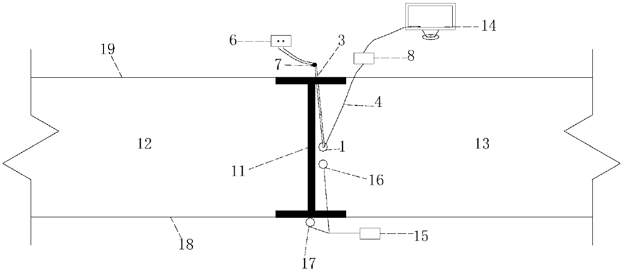
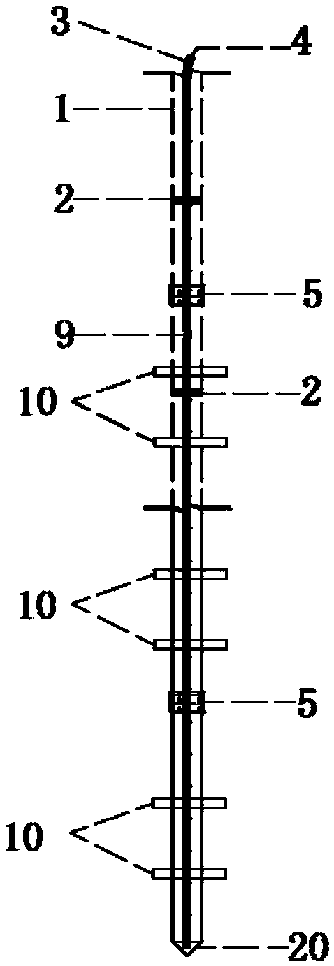
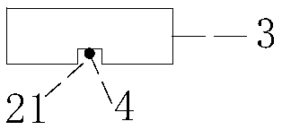
[0025] The ground connection wall joint leakage monitoring and repairing device based on optical fiber temperature measurement includes an I-shaped steel joint 11, and the grooves on both sides of the I-shaped steel joint 11 are respectively connected with the reinforcement cage of the leading groove section 12 of the underground diaphragm wall and the follow-up of the underground diaphragm wall. The steel cage connection of the groove section 13, the connection seam of the underground diaphragm wall is formed between the leading groove section 12 of the underground diaphragm wall and the subsequent groove section 13 of the underground diaphragm wall, and the I-shaped steel joint 11 extends along the connection seam of the underground diaphragm wall. It is characterized in that, It includes a hollow floral tube 1, which extends along the connecting joint of the underground diaphragm wall. The hollow floral tube 1 is fixed in the groove of the I-shaped steel joint 11 facing the s...


PUM


Abstract

The invention discloses a ground connection wall joint leakage monitoring repair device based on optical fiber temperature measuring. The device comprises a hollow floral tube, the hollow floral tubeextends along an underground connection wall connection joint, the hollow floral tube is fixed to a groove, towards the underground continuous wall follow-up groove section, in an H-shaped steel jointthrough a positioning steel ring, a heating zone is arranged inside the hollow floral tube in the longitudinal direction of the hollow floral tube, an optical fiber placement linear groove is formedin the heating zone in the longitudinal direction of the heating zone, an optical fiber temperature sensor is arranged inside the optical fiber placement linear groove, the optical fiber temperature sensor is connected with a multi-channel optical fiber demodulator through a connecting optical fiber, and the heating zone is connected with a temperature controller. The invention further discloses aground connection wall joint leakage monitoring repair method based on optical fiber temperature measuring. Underground connection wall groove section joint leakage water advanced detecting, monitoring and repairing are achieved, and safety risk caused by leakage after excavation can be avoided.

Description

technical field [0001] The invention belongs to the technical field of foundation pit engineering detection, monitoring and emergency repair, and more specifically relates to a ground connection wall joint leakage monitoring and repairing device based on optical fiber temperature measurement, and also relates to a ground connection wall joint leakage monitoring and repairing based on optical fiber temperature measurement method. Background technique [0002] Due to its high rigidity, good integrity, and good impermeability of the wall, the underground diaphragm wall is recognized as the best supporting structure in deep foundation pit engineering. However, the underground diaphragm wall is constructed in sections of grooves, and the joints of the grooves are not densely poured, so the leakage problem is not uncommon, which has become one of the key inducing factors of underground diaphragm wall safety accidents. The advanced detection, real-time monitoring and in-situ repai...

Claims


Application Information

Patent Timeline
Patent Type & Authority Applications(China)
IPC IPC(8): E02D33/00E02D37/00E02D29/16E02D15/04
CPCE02D15/04E02D29/16E02D33/00E02D37/00E02D2250/003
Inventor 郑允陈从新张亚鹏邵勇孙朝燚
Owner INST OF ROCK & SOIL MECHANICS CHINESE ACAD OF SCI
Learn More