An automatic truss cutting device

A technology for cutting equipment and trusses, which is applied in the field of automatic truss cutting equipment, and can solve problems such as burrs on the surface of steel bars, easy external events, and high labor intensity.

Active Publication Date: 2021-04-09
HUNAN SANY KUAIERJU RESIDENTIAL IND CO LTD
View PDF9 Cites 0 Cited by
  • Summary
  • Abstract
  • Description
  • Claims
  • Application Information

AI Technical Summary

Problems solved by technology

[0004] 1) The existing truss production equipment cannot make the truss arbitrarily sized. The truss machine is in a fixed position when cutting, and the length of the truss produced is an integer of 100mm. It is cut by a manual grinding wheel cutting machine, and its size cannot be cut. ensure
[0005] 2) The existing production method needs to produce a large number of trusses first, and then carry out the second cutting, the production efficiency is low, and the production site occupied is large
[0006] 3) The existing production method is labor-intensive. For example, when the length of the cut truss is long, at least two people are required to carry out the handling operation at the same time. There are many burrs on the surface of the steel bar, and accidents are prone to occur during operation, resulting in personal injury.
[0007] 4) It is impossible to produce trusses in time according to the requirements of the production order and send the trusses to the designated position of the production line according to the requirements of the production beat, so as to meet the requirements of the automated production line and improve production efficiency

Method used


Image

  • An automatic truss cutting device
  • An automatic truss cutting device
  • An automatic truss cutting device

Examples


Embodiment 1

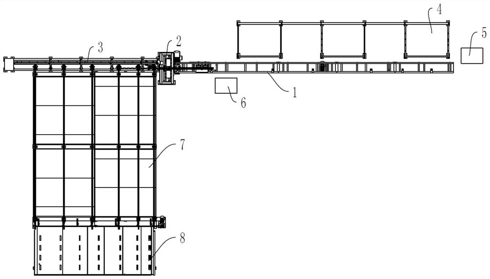
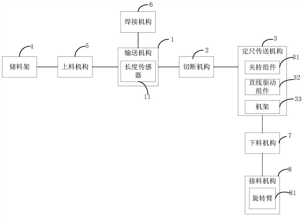
[0036] Please also refer to figure 1 with figure 2 , the present embodiment provides an automatic truss cutting device, including a conveying mechanism 1 , a cutting mechanism 2 and a length-defining conveying mechanism 3 . The cutting mechanism 2 is located between the conveying mechanism 1 and the fixed length conveying mechanism 3. The cutting mechanism 2 is used to cut off the truss. When the conveying mechanism 1 transports the truss to the fixed-length conveying mechanism 3, the fixed-length conveying mechanism 3 stops after conveying the truss according to a preset conveying distance, and the cutting mechanism 2 cuts off the truss.

[0037] As mentioned above, the conveying mechanism 1 is a kind of conveying device, which can drive / drive the truss to continuously move to the cutting mechanism 2, eliminating the need for manual material pushing. The cutting mechanism 2 can be an existing cutting device, and its cutting execution part is a cutter, which is driven to mo...


PUM


Abstract

The automatic truss cutting device of the present invention includes a conveying mechanism, a cutting mechanism and a fixed-length conveying mechanism; the cutting mechanism is arranged between the conveying mechanism and the fixed-length conveying mechanism, and the cutting mechanism is used for cutting the truss, the transmission mechanism and the fixed-length conveying mechanism. The direction is the same and the conveying mechanism conveys the truss to the cutting mechanism; when the conveying mechanism conveys the truss to the fixed-length conveying mechanism, the fixed-length conveying mechanism stops after transmitting the truss according to the preset transmission distance, and the cutting mechanism cuts the truss. The fixed-length conveying mechanism drives the truss to move, and the distance that the truss is transmitted from the cutting mechanism is controlled by controlling the moving distance of the fixed-length conveying mechanism to drive the truss, thereby controlling the cutting length of the truss. Since the transmission distance of the fixed-length conveying mechanism can be adjusted arbitrarily, Therefore, the cutting length of the truss can be adjusted arbitrarily, and it is a truss cutting that can automatically convey the truss, the cutting length of the truss can be adjusted arbitrarily, the cutting size is more accurate, the production safety is high, and the efficiency is high.

Description

technical field [0001] The invention relates to the field of truss production equipment, in particular to an automatic truss cutting equipment. Background technique [0002] Trusses are mainly used on prefabricated floors. With the wide application of prefabricated buildings, the average annual growth rate of trusses used in prefabricated floors is relatively large. After the current steel bar truss production machine cuts the truss, its cutting position is generally at two fixed positions, one is the welding place between the upper chord steel bar and the web bar steel bar, and the other is the welding site between the lower chord bar and the web bar bar bar. The length of the truss is usually an integer multiple of 100mm, and it is impossible to cut off any truss. According to the existing production level, the trusses are generally produced at a length of not less than 9 meters each, and then placed together, and then according to the requirements of the components, the ...

Claims


Application Information

Patent Timeline
Patent Type & Authority Patents(China)
IPC IPC(8): B23P23/04B23D31/00B23K31/02B23Q7/14
CPCB23D31/002B23K31/02B23P23/04B23Q7/14
Inventor 刘建芬
Owner HUNAN SANY KUAIERJU RESIDENTIAL IND CO LTD
Why Eureka
Try Eureka