
Device and method for manufacturing multi-purpose partition wall

A multi-purpose planting trough technology, applied in the direction of automatic watering devices, botanical equipment and methods, applications, etc., can solve the problems of multiple vertical distances, threats to the lives of the masses, and unusable elevators, etc., to reduce the process and Cost, increase the overall appearance, improve the effect of survival rate

Inactive Publication Date: 2019-04-05
CHINA THREE GORGES UNIV
View PDF5 Cites 0 Cited by
  • Summary
  • Abstract
  • Description
  • Claims
  • Application Information

AI Technical Summary

Problems solved by technology

[0003] With the development of the economy, the scale of high-rise buildings is getting bigger and bigger, the functions are more and more diversified, and the design is becoming more and more innovative, with more floors and longer vertical distances; once a fire breaks out in a high-rise building, the climbing fire truck cannot play its role Effectiveness, the elevator cannot be used, so that it takes a long time to evacuate the people in the building to the ground or a safe area, and the rescue work becomes more difficult, which seriously threatens the safety of people's lives
Moreover, fire-fighting equipment is not equipped in the families where many residents live, and they cannot be well extinguished when a fire breaks out.
In many buildings today, non-load-bearing walls are only used to separate rooms and have not been well utilized

Method used


Image

  • Device and method for manufacturing multi-purpose partition wall
  • Device and method for manufacturing multi-purpose partition wall

Examples


Embodiment 1

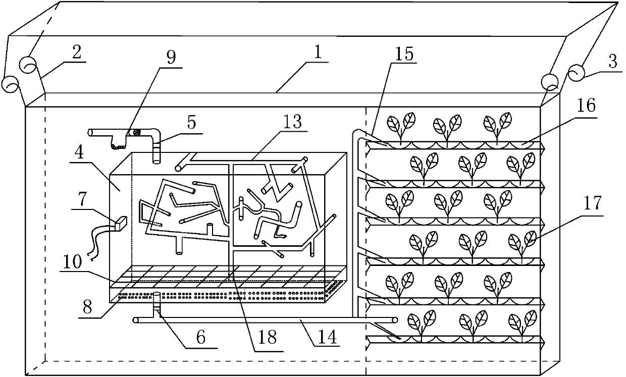
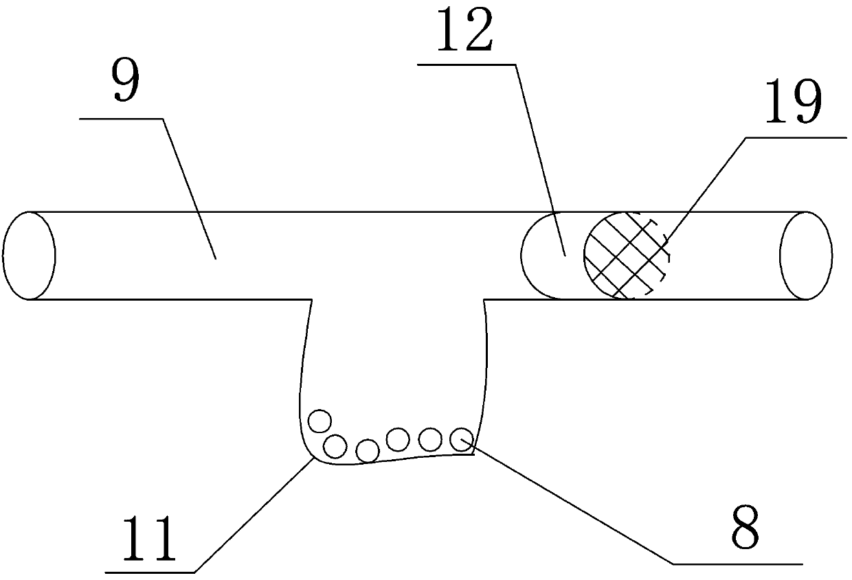
[0038] See Figure 1-2 , A device for making a multi-purpose partition wall, which includes a steel frame structure 1, and hooks 2 are fixedly arranged at the four top corners of the steel frame structure 1, and the hooks 2 are hooked on the wall frame through the hooks 3 On the beam of the structure; the steel frame structure 1 is fixedly installed with a transparent water tank 4, a water outlet is reserved at the bottom of the transparent water tank 4, and a water tank outlet valve 6 is installed at the position of the water outlet, and is reserved on the top of the transparent water tank 4 In the water inlet, a water tank inlet valve 5 is installed at the position of the water inlet; a planting area is provided on both outer sides of the transparent water tank 4, and a multi-layer planting tank 16 is installed inside the planting area; the water tank outlet valve 6 is located in the pipeline A three-way joint is installed on it to divide it into a water exchange channel and ...

Embodiment 2

[0047] Any one of the methods for making a device for a multi-purpose partition wall includes the following steps:

[0048] Step1: Material preparation: prepare light steel, transparent water tank 4, hook 2, shackle 3, transparent PC tube 13, main duct 14, shunt duct 15, activated carbon 8, barbed wire 10, valve and fixed rod 18;

[0049] Step2: Make steel frame structure 1: Use measuring tools to measure the size of the non-load-bearing wall, make steel frame structure 1 according to the measured data, and weld hooks 2 on the four top corners of steel frame structure 1;

[0050] Step3: Fixing the steel frame structure 1: Install the shackle 3 on the beam of the house frame, and connect the hook 2 on the steel frame structure 1 with the shackle 3 to fix the steel frame structure;

[0051] Step4: Design of the transparent water tank 4: Reserve a water outlet and water inlet at the bottom and top of the transparent water tank 4 respectively, and install the water tank outlet valve 6 and ...


PUM


Abstract

The invention discloses a device and method for manufacturing a multi-purpose partition wall. The device comprises a steel frame structure, four corners of the steel frame structure are fixedly provided with hooks, and the hooks are hung on a beam of the steel frame structure through shackles; a transparent water tank is fixedly installed in the steel frame structure, a water outlet hole is reserved in the bottom of the transparent water tank, a water tank water outlet valve is installed at the water outlet hole, a water inlet hole is reserved in the top of the transparent water tank, and a water tank water inlet valve is installed at the water inlet hole; planting areas are arranged at the two sides of the exterior of the transparent water tank, and multiple layers of planting grooves areformed in the planting areas. The function of a non-bearing wall can be fully exerted, and a wall body can be fully utilized for indoor decoration; when a fire occurs, water in the water tank can besprayed out to extinguish the fire, the upward spreading speed of smoke is reduced, and the survival probability of personnel inside the building is increased.

Description

Technical field [0001] The present invention is mainly used for non-load-bearing walls in buildings, so that the non-load-bearing walls can be used as walls with fire-fighting and landscape design functions without changing the nature of the non-bearing walls, and specifically relates to a multi-purpose partition wall device and method. Background technique [0002] Our country has a large population and tight land use. In order to better meet people's living and living needs, high-rise buildings have been built in many places. However, the unique structure and function of high-rise buildings also pose a huge threat to people's lives and property. Affected by the chimney effect, once a fire occurs in a high-rise building, there are more building shafts and pipes, which will easily cause the fire to spread faster. Related experiments have shown that the diffusion rate of smoke along the stairs or shafts in high-rise buildings can reach 3~4m / s, which can swallow the entire floor ...

Claims


Application Information

Patent Timeline
Patent Type & Authority Applications(China)
IPC IPC(8): A01K63/00A01K63/04A01G9/029A01G27/02
CPCA01G27/02A01K63/003A01K63/006A01K63/042A01K63/045A01G9/029
Inventor 刘杰高素芳莫承林孙涛黎照兰俊韩绍康谢晓康唐洪宇李洪亚周文俊高进张罗送李骁霖罗越文周克虎姜锋
Owner CHINA THREE GORGES UNIV
Learn More