Joint arrangement for an articulated shaft

A joint device and journal technology, which is applied in the field of joint devices, can solve problems such as high load and bearing failure, and achieve the effect of reducing load

Active Publication Date: 2019-04-02
VOITH PATENT GMBH
View PDF5 Cites 0 Cited by
  • Summary
  • Abstract
  • Description
  • Claims
  • Application Information

AI Technical Summary

Problems solved by technology

If these particles roll between the bearing raceways and the rolling elements, they c

Method used


Image

  • Joint arrangement for an articulated shaft
  • Joint arrangement for an articulated shaft
  • Joint arrangement for an articulated shaft

Examples


Embodiment Construction

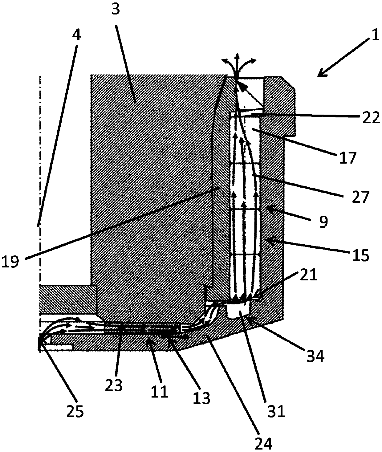
[0041] exist figure 1 The joint device 1 is shown in . The joint arrangement has a journal 3 with an axial axis 4 . Such as Figure 11 As shown in , a radial bearing 9 and an axial bearing 11 are provided for supporting the journal 3 in the joint fork 5 . In the exemplary embodiment shown, a rolling bearing 15 with rolling elements 17 is provided as radial bearing 9 . The rolling bodies 17 are supported by means of a bearing shell 19 in a cover 24 coaxially surrounding the journal 3 . The rolling element 17 is supported by a stop 21 formed on the cover 24 and cooperating with the spring element 22 . The journal 3 has a free end 23 . A slide bearing 13 is arranged as axial bearing 11 between the cover 24 and the free end of the journal 23 .

[0042] To lubricate the bearings 9 and 11 , lubricant is introduced through the lubricant opening 25 . The lubricant openings are generally formed in the cover 24 . Due to the movement of the joint arrangement 1 , the lubricant is ...


PUM


Abstract

The invention relates to a joint arrangement (1) for an articulated shaft. The joint arrangement (1) comprises a journal (3). The journal is mounted in a fork bore (7). The journal has a free axial end (23). The free axial end has a covering (24). The covering has an annular groove (31), wherein the groove (31) comprises an opening (32), and said opening is oriented in the direction of the free axial end (23) of the journal (3).

Description

technical field [0001] The invention relates to a joint device for an articulated shaft. Background technique [0002] Articulating shafts for transmitting torque are generally well known and common. The joint or universal joint here typically consists of a cross journal and two forks rotated by 90° relative to each other, wherein each journal of the cross journal is arranged in the fork hole of the respective axis of the fork middle. In order to permanently transmit correspondingly high torques with the articulated shaft, the journal is correspondingly supported in the fork opening, since a continuous pivoting movement of the journal relative to the fork opening takes place during operation. Bearings are regularly lubricated with a slip agent such as, for example, bearing grease. [0003] In particular, very high torques of the order of magnitude of several thousand kilonewton meters are transmitted in the heavily loaded joint shafts, which are arranged, in particular, i...

Claims


Application Information

Patent Timeline
IPC IPC(8): F16D3/00F16D3/38F16D3/202
CPCF16D3/385F16D2300/08F16D2300/06F16C19/545F16C21/005F16C19/52F16C33/6629
Inventor 彼得·格拉温霍夫
Owner VOITH PATENT GMBH
Why Eureka
Try Eureka