Small-size electromagnetic relay

An electromagnetic relay and relay technology, applied in electromagnetic relays, electromagnetic relay details, relays, etc., can solve the problems of high production cost, cumbersome operation, complicated assembly, etc., and achieve the effects of simple operation, convenient use and simple assembly structure.

Pending Publication Date: 2019-04-02
ZHEJIANG CHINT ELECTRIC CO LTD
View PDF8 Cites 0 Cited by
  • Summary
  • Abstract
  • Description
  • Claims
  • Application Information

AI Technical Summary

Problems solved by technology

[0003] 1. The operation is cumbersome and there is no state locking function;
[0004] 2. The transmission chain precision requirements for test switches and moving contact components are high, so the precision of product components needs to be strictly required, resulting in high production costs;
[0005] 3. There is no status indication text, which is not convenient for users to use directly;
[0006] 4. There is no state locking function, which is easy to be accidentally touched by the user, causing the electromagnetic relay to malfunction, damage the product, and even cause a safety accident;
[0007] 5. The product has many parts and complex assembly, which is not conducive to improving production efficiency;
[0008] 6. Product switching test status needs tools to assist

Method used


Image

  • Small-size electromagnetic relay
  • Small-size electromagnetic relay
  • Small-size electromagnetic relay

Examples


Embodiment Construction

[0056] The following is attached Figures 1 to 23 The given examples further illustrate the specific implementation of the small electromagnetic relay of the present invention. The small electromagnetic relay of the present invention is not limited to the description of the following embodiments.

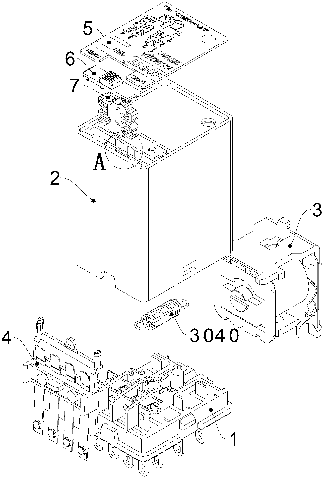
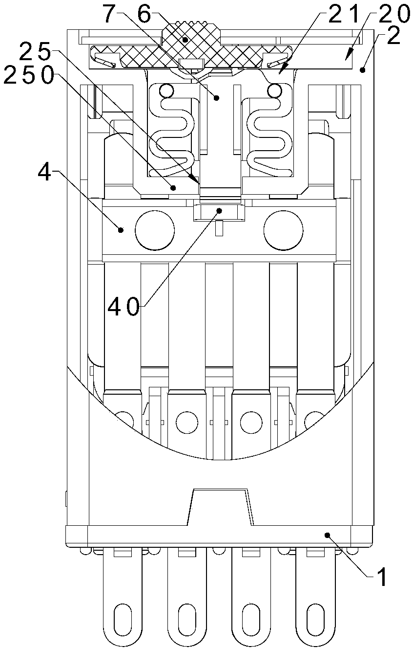
[0057] The small electromagnetic relay of the present invention comprises a relay casing, an electromagnetic system 3 arranged inside the relay casing, a contact system arranged on one side of the electromagnetic system 3 and a test switch arranged on the top of the contact system to cooperate with it, and the contact system includes The moving contact assembly 4 and the static contact group 15 matched with the moving contact assembly 4;

[0058] The test switch includes a switch 6 horizontally slidably arranged on the upper part of the relay housing and a push rod 7 arranged below the switch 6 to cooperate with it. The movable contact assembly 4 includes a boss 40 arranged on one ...


PUM


Abstract

The present invention relates to the field of low-voltage electrical appliances, especially to a small-sized electromagnetic relay. The small-sized electromagnetic relay comprises a relay housing, anelectromagnetic system disposed inside the relay housing, a contact system disposed on one side of the electromagnetic system and matched with the electromagnetic system, and a test switch arranged atthe upper portion of the contact system and matched with the contact system. The contact system comprises a movable contact module and a fixed contact module cooperated with the moving contact module; the test switch comprises a switch horizontally slidably disposed at the upper portion of the relay housing and a push rod arranged at the lower portion of the switch and cooperated with the switch,the moving contact module comprises a boss arranged at one side of the moving contact module, the upper end of the push rod is sliding cooperated with the switch, the lower end of the push rod is cooperated with the boss, the switch horizontally slides to move the push rod downwards, and the boss drives the motion of the moving contact module. The small-sized electromagnetic relay is simple in structure, convenient to operate and fast in assembling, and has state locking and indication functions.

Description

technical field [0001] The invention relates to the field of low-voltage electrical appliances, in particular to a small relay, in particular to a small electromagnetic relay provided with a test switch. Background technique [0002] In the existing small electromagnetic relay, the test switch is a mechanical component arranged on the upper part of the relay, which cooperates with the raised feature arranged on the moving contact assembly, so as to realize manual operation when the equipment or circuit controlled by the small electromagnetic relay needs to be tested. The mechanical component enables the on / off function of the small electromagnetic relay through the raised feature. At present, there are various implementation schemes of test switches on the market, and most of them have the following problems: [0003] 1. The operation is cumbersome and there is no state locking function; [0004] 2. The transmission chain precision requirements for test switches and moving...

Claims


Application Information

Patent Timeline
Patent Type & Authority Applications(China)
IPC IPC(8): H01H50/02H01H50/64
CPCH01H50/021H01H50/64
Inventor 王琦王联长蒲启成
Owner ZHEJIANG CHINT ELECTRIC CO LTD
Why Eureka
Try Eureka