
Tunable filter

A filter and optical fiber connector technology, applied in the field of optical filters, can solve problems such as being susceptible to temperature changes and difficult to achieve miniaturized packaging

Active Publication Date: 2019-04-02
ZHUHAI GUANGKU TECH CO LTD
View PDF27 Cites 7 Cited by
  • Summary
  • Abstract
  • Description
  • Claims
  • Application Information

AI Technical Summary

Problems solved by technology

[0003] There are still many problems and deficiencies in the practical application of tunable optical fiber FP filters, such as being susceptible to temperature changes, and a change in ambient temperature of 1 degree Celsius often causes changes in the wavelength of optical fiber FP filters of at least a few nanometers
The solution in the prior art is to use a sealed space to install a refrigerator or a thermostat to achieve temperature control, which will inevitably increase the complexity of the structure and make it difficult to achieve miniaturized packaging

Method used


Image

  • Tunable filter
  • Tunable filter
  • Tunable filter

Examples


no. 1 example

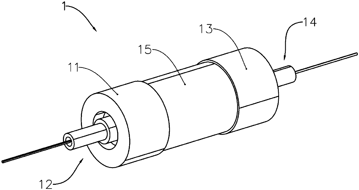
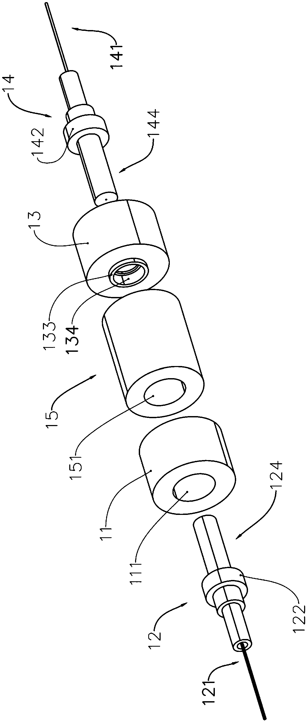
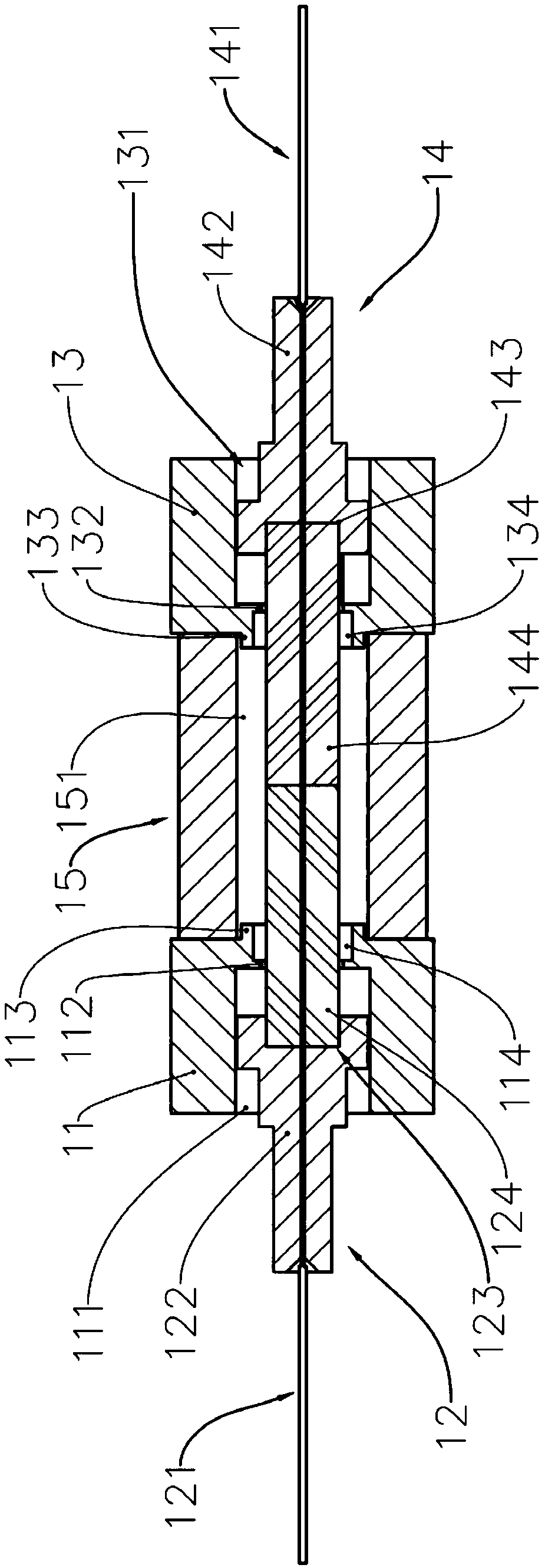
[0026] refer to Figure 1 to Figure 3 , the tunable filter 1 includes a first fixing member 11, a first optical fiber connector 12, a second fixing member 13, a second optical fiber connector 14 and a piezoelectric ceramic 15, and the first optical fiber connector 12 includes a first connection housing 122, the first fiber core 121 and the first fiber ferrule 124, the first connection housing 122 is provided with a mounting groove 123, the first fiber ferrule 124 is fixedly arranged on the installation groove 123 of the first connection housing 122, the first The optical fiber ferrule 124 is arranged along the optical path direction, the axis of the first optical fiber ferrule 124 is parallel to the optical path direction, and the first optical fiber core 121 extends into the first optical fiber ferrule 124 through the first connection housing 122 along the optical path direction, The end of the first fiber core 121 extends to the exit end of the first fiber ferrule 124 , and ...

no. 2 example

[0035] refer to Figure 4 to Figure 6 , the tunable filter 2 includes a first fixing member 21, a first optical fiber connector 22, a second fixing member 23, a second optical fiber connector 24 and a piezoelectric ceramic 25, and the first optical fiber connector 22 includes a connection housing 222, The first fiber core 221 and the first fiber optic ferrule 224, the connection housing 222 is provided with a mounting groove 223, the first fiber optic ferrule 224 is fixedly arranged on the mounting groove 223 of the connection housing 222, the first fiber optic ferrule 224 along the optical path direction, the axial direction of the first fiber ferrule 224 is parallel to the direction of the optical path, the first fiber core 221 passes through the connection housing 222 and extends into the first fiber ferrule 224 along the direction of the optical path, and the end of the first fiber core 221 Extending to the exit end of the first fiber ferrule 224 , the signal light transmi...


PUM


Abstract

The invention provides a tunable filter, comprising two fixing members, two fiber connectors, and a piezoceramic. The fixing member penetrates and is provided with mounting through holes along a direction of an optical-path. The fiber optic connector comprises a connecting shell, a fiber core, and a fiber insertion core. The fiber insertion core is fixedly arranged on the connecting shell. The fiber core penetrates the connecting shell along the direction of the optical-path and extends into the fiber insertion core. The connecting shell is fixedly mounted in the mounting through hole. The piezoceramic penetrates and is provided with a receiving through hole along the direction of the optical-path. The piezoceramic is connected between the fixing members along the direction of the optical-path. The mounting through hole communicates with the receiving through hole in sequence. The exit ends of the two fiber insertion cores are oppositely arranged in the receiving through holes. The piezoceramic is connected between the fixing members, and the exit end of the first fiber insertion core and the exit end of the second fiber insertion core are oppositely arranged in the receiving through holes, then an F-P resonant cavity is formed, and the distance between the fixing members is finely adjusted by using piezoelectric effect characteristics of the piezoceramic, so that the filter can precisely adjust the filtering.

Description

technical field [0001] The invention relates to the field of optical filters, in particular to an adjustable filter. Background technique [0002] With the development and maturity of fiber grating sensing technology, wavelength demodulation technology has attracted more and more attention and attention. The wavelength demodulation system based on tunable optical fiber FP filter has the advantages of low cost, fast response and high resolution, and has been widely used. The tunable optical fiber FP filter is the core device of the whole system, and its performance largely determines the performance of the whole demodulation system. In optical communication systems, tunable FP filters are mainly used for demultiplexing and signal demodulation of wavelength division multiplexing, and filters have become mainstream devices. In addition, FP devices can also be used as signal filters in fiber amplifiers, and also have important applications in fiber lasers and spectrum analysis...

Claims


Application Information

Patent Timeline
Patent Type & Authority Applications(China)
IPC IPC(8): G02B6/293
CPCG02B6/29359G02B6/29395G02B6/29398
Inventor 傅谦许克畇刘勋
Owner ZHUHAI GUANGKU TECH CO LTD
Learn More