Blade automatic forming equipment

A molding equipment, fully automatic technology, applied in the direction of metal processing equipment, feeding device, positioning device, etc., can solve the problems of difficult control of pressure, need for artificial filling, low production efficiency, etc., to achieve convenient and safe loading and unloading time, saving The effect of loading and unloading time and improving processing efficiency

Active Publication Date: 2019-04-02
RES INST OF ZHEJIANG UNIV TAIZHOU
View PDF5 Cites 3 Cited by
  • Summary
  • Abstract
  • Description
  • Claims
  • Application Information

AI Technical Summary

Problems solved by technology

[0002] In the prior art, blade forming is formed by punching raw material blades, and the equipment used is stamping forming equipment, which includes a punching machine and a punching die. When in use, the blade is manually placed on the punching die, and the punching machine punches the blade into shape. The disadvantages are that manual filling is required, the safety performance is low, the pressure is difficult to control, the production efficiency is low, and in the process of mass production, the error between the same batch of blades is relatively large. Therefore, there is an urgent need for a fully automatic blade forming equipment to solve the problem. above question

Method used


Image

  • Blade automatic forming equipment
  • Blade automatic forming equipment
  • Blade automatic forming equipment

Examples


Embodiment Construction

[0022] Before describing the embodiments in detail, it should be understood that the present invention is not limited to the detailed structures or arrangements of elements described herein below or in the accompanying drawings. The present invention can be implemented in other ways. Also, it should be understood that the phraseology and terminology used herein are for descriptive purposes only and should not be interpreted as limiting. The terms "including", "comprising", "having" and similar expressions used herein are meant to include the items listed thereafter, their equivalents and other additional items. In particular, when "a certain element" is described, the present invention does not limit the number of the element to one, but may also include a plurality.

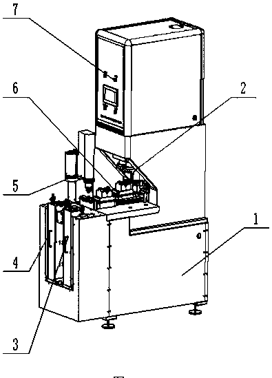
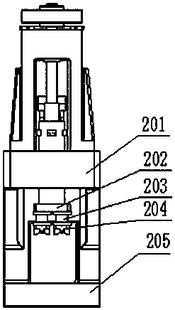
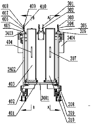
[0023] see Figure 1-Figure 8 , the present invention provides a technical solution: including a frame 1, a stamping mechanism 2, a feeding mechanism 3, a blanking mechanism 4, a four-axis manipulator 5, a sli...


PUM


Abstract

The invention provides blade automatic forming equipment, which includes a rack, a stamping mechanism, a feeding mechanism, a discharging mechanism, a four-axis manipulator, a sliding rail mechanism and a protective cover. The protective cover is fixed to the upper end face of a power package bracket, the feeding mechanism is installed on the front end face of the rack, and the discharging mechanism is installed on the front end face of the rack and assembled on the left side of the feeding mechanism; and the four-axis manipulator is installed on the edge position of the left side of the upperend face of a working table, the sliding rail mechanism is fixed to the upper end face of the working table and installed on the right side of the four-axis manipulator, and the stamping mechanism isassembled in the rack and installed on the upper side of the sliding rail mechanism. According to the blade automatic forming equipment, the feeding and discharging time is saved, the processing efficiency is improved, the position and pressure are precisely controlled, the quality of stamping forming products is stable, and the accuracy is high.

Description

technical field [0001] The invention is a fully automatic forming equipment for blades, which belongs to the field of fully automatic forming equipment for blades. Background technique [0002] In the prior art, blade forming is formed by punching raw material blades, and the equipment used is stamping forming equipment, which includes a punching machine and a punching die. When in use, the blade is manually placed on the punching die, and the punching machine punches the blade into shape. The disadvantages are that manual filling is required, the safety performance is low, the pressure is difficult to control, the production efficiency is low, and in the process of mass production, the error between the same batch of blades is relatively large. Therefore, there is an urgent need for a fully automatic blade forming equipment to solve the problem. above question. Contents of the invention [0003] Aiming at the deficiencies in the prior art, the purpose of the present inve...

Claims


Application Information

Patent Timeline
Patent Type & Authority Applications(China)
IPC IPC(8): B21D28/02B21D28/14B21D43/13B21C51/00
CPCB21C51/00B21D28/02B21D28/14B21D43/13
Inventor 杨利利李广平葛正陈其吴日远崔坤彤王维锐徐子轩
Owner RES INST OF ZHEJIANG UNIV TAIZHOU
Why Eureka
Try Eureka