
Method and device for dispensing positioning based on machine vision

A technology of machine vision and positioning method, which is applied to devices and coatings that apply liquid to the surface, can solve the problems of high cost, low efficiency, cumbersome steps, etc., achieve good positioning accuracy, reduce costs, and simple dispensing steps Effect

Active Publication Date: 2019-04-02
SHENZHEN TENSUN IND EQUIP
View PDF6 Cites 14 Cited by
  • Summary
  • Abstract
  • Description
  • Claims
  • Application Information

AI Technical Summary

Problems solved by technology

[0005] The purpose of the present invention is to provide a machine vision-based dispensing positioning method and device for the technical problems existing in the prior art, which mainly solves the problems of high cost, cumbersome steps and low efficiency of the dispensing positioning method in the prior art

Method used


Image

  • Method and device for dispensing positioning based on machine vision
  • Method and device for dispensing positioning based on machine vision
  • Method and device for dispensing positioning based on machine vision

Examples


Embodiment 1

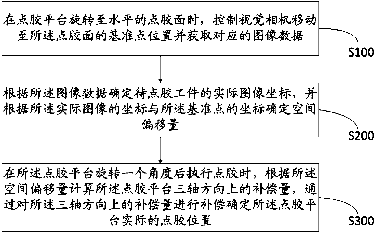
[0057] refer to figure 1 As shown, it is a flow chart of the steps of the machine vision-based dispensing positioning method described in the embodiment of the present invention, including the following steps:

[0058] S100: When the glue dispensing platform rotates to a horizontal glue dispensing surface, control the visual camera to move to a reference point position of the glue dispensing surface and acquire corresponding image data.

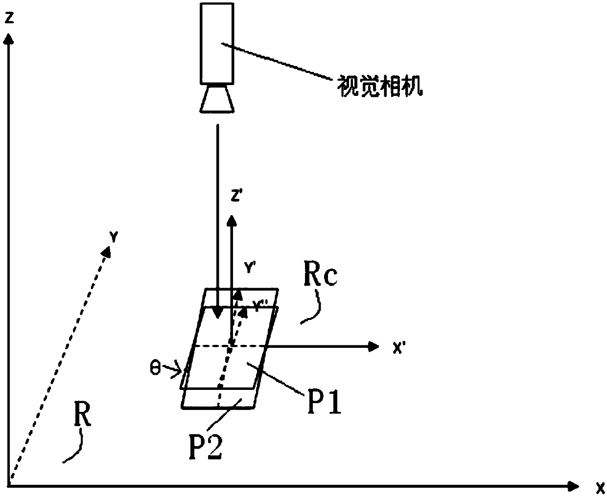
[0059] When the dispensing platform rotates to the horizontal dispensing surface, the visual camera is controlled to move to the reference point position of the dispensing surface. In this embodiment, the reference point position is the Mark point position of the dispensing surface of the workpiece to be dispensed. , that is, the point used for machine welding positioning; at this time, refer to figure 2 The coordinate schematic diagram of the dispensing positioning method shown, establishes a space Cartesian coordinate system R in the spac...

Embodiment 2

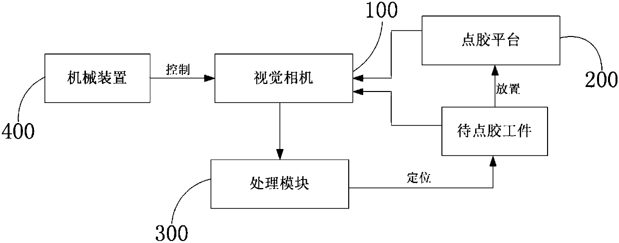
[0083] The embodiment of the present invention also provides a dispensing positioning device based on machine vision, which is applied to the dispensing positioning method based on machine vision described in the above embodiment. image 3 As shown, the dispensing positioning device includes a visual camera 100, a dispensing platform 200, a processing module 300 and a mechanical device 400 for controlling the movement of the visual camera;

[0084] The dispensing platform 200 is used to place workpieces to be dispensed; the visual camera 100 moves to the dispensing surface under the control of the mechanical device 400 when the dispensing platform 200 rotates to the horizontal dispensing surface Acquire corresponding image data at the reference point position; the processing module 300 is used to determine the actual image coordinates of the workpiece to be dispensed according to the image data obtained by the visual camera 100, and according to the coordinates of the actual im...


PUM


Abstract

The invention discloses a method and a device for dispensing positioning based on machine vision, and relates to the technical field of dispensing. The method comprises the following steps: controlling a visual camera to move to a reference point position of a dispensing surface when a dispensing platform rotates to a horizontal dispensing surface, and obtaining corresponding image data; determining actual image coordinates of a to-be-dispensed workpiece according to the image data, and determining spatial offset according to coordinates of an actual image and coordinates of the reference point; when the dispensing platform rotates at an angle and performs dispensing, calculating compensation quantity of the dispensing platform in three-axis directions according to the spatial offset, anddetermining an actual dispensing position of the dispensing platform through compensating the compensation quantity on the three-axis directions. The method has good positioning accuracy, reduces cost, and has simple dispensing steps, and improves dispensing efficiency in a production process.

Description

technical field [0001] The invention relates to the field of glue dispensing technology, in particular to a machine vision-based glue dispensing positioning method and device. Background technique [0002] With the advancement of machine vision technology, the image vision system has been widely used in the field of product production. For example, the dispensing method of the product is obtained by selecting the shape with obvious characteristics as the positioning object of the camera, and then comparing it with the preset template position. offset to compensate for the dispensing position. [0003] However, the dispensing platform of this dispensing method is a plane, and its dispensing position can only complete compensation on the plane; when the dispensing platform rotates to a certain angle, this dispensing method cannot meet the needs of production. A height sensor needs to be added to measure the height of the platform. [0004] Therefore, the dispensing positioni...

Claims


Application Information

Patent Timeline
Patent Type & Authority Applications(China)
IPC IPC(8): B05C11/10
CPCB05C11/1015
Inventor 卢国明黎春洁
Owner SHENZHEN TENSUN IND EQUIP
Learn More