Display panel and display device

A display panel and display area technology, applied in optics, instruments, electrical components, etc., can solve the problems of dense wiring at the edge of the perforated area, large coupling between wiring, and occupation of the display area of ​​the display panel, etc., to improve display stability Sexuality, increase the screen ratio, and reduce the number of effects

Active Publication Date: 2019-03-29
XIAMEN TIANMA MICRO ELECTRONICS
View PDF12 Cites 20 Cited by
  • Summary
  • Abstract
  • Description
  • Claims
  • Application Information

AI Technical Summary

Problems solved by technology

[0003] Since the punched area is located in the display area, when the various traces in the display panel extend to the punched area, they will continue to extend along the edge of the punched area, resulting in very dense traces on the edge of the punched area
Excessive traces lead to large edges of the punched area, occupying the display area of ​​the display panel and affecting the screen-to-body ratio of the display panel; at the same time, due to the small distance between the traces, the coupling effect between the traces is large, which affects show stability

Method used


Image

  • Display panel and display device
  • Display panel and display device
  • Display panel and display device

Examples


Embodiment Construction

[0019] In order to make the purpose, technical solution and advantages of the present invention clearer, the technical solution of the present invention will be fully described below through specific implementation in combination with the drawings in the embodiments of the present invention. Apparently, the described embodiments are some embodiments of the present invention, rather than all embodiments. Based on the embodiments of the present invention, all other embodiments obtained by persons of ordinary skill in the art without making creative efforts, All fall within the protection scope of the present invention.

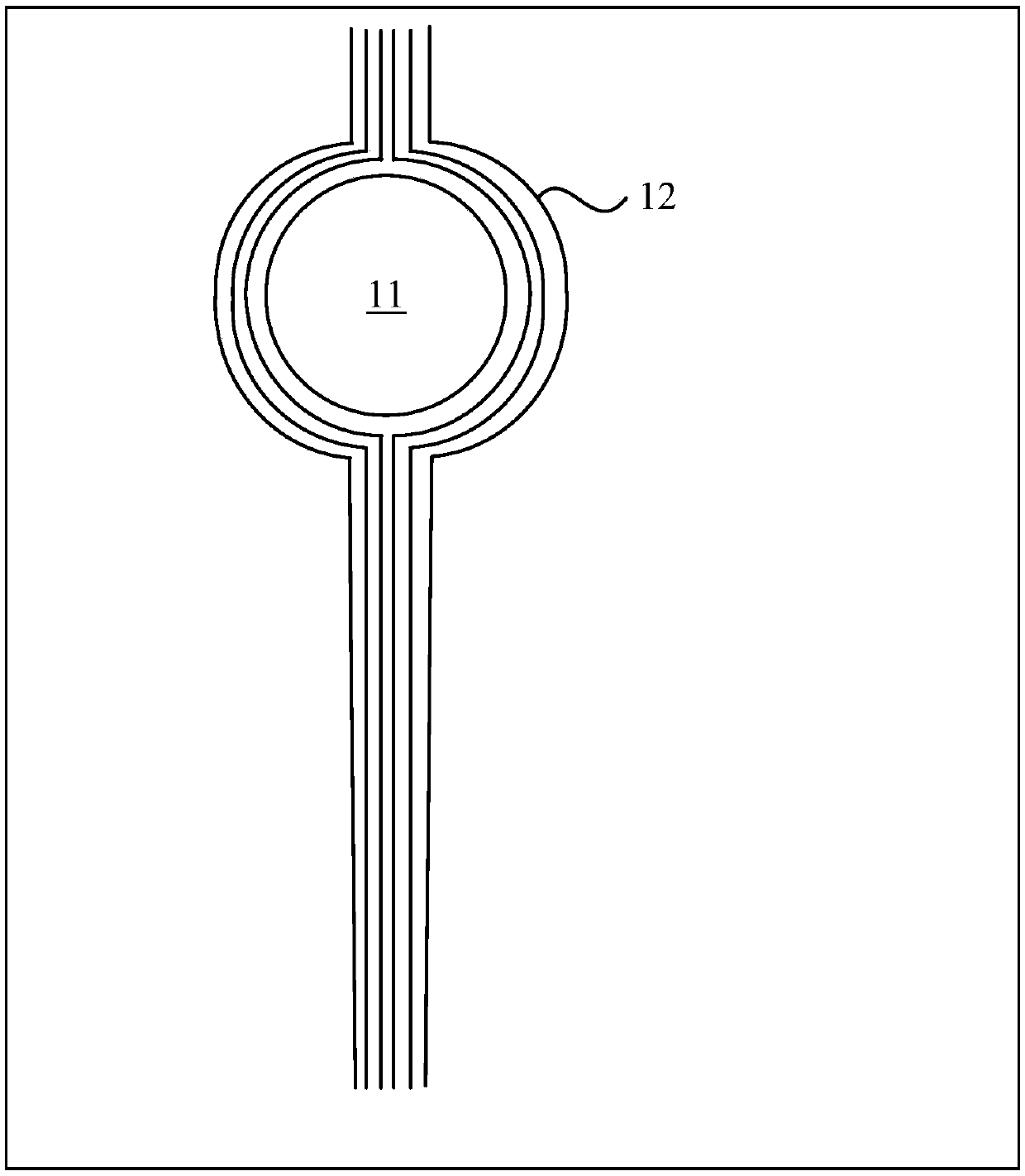
[0020] figure 1 It is a structural schematic diagram of a display panel in the prior art, such as figure 1 As shown, through holes 11 and various signal traces are formed in the display panel, figure 1 Only the data signal line 12 is taken as an example for illustration. The data signal wiring 12 is used to provide data signals to a column of pixel units, so ...


PUM


Abstract

The invention discloses a display panel and a display device. The display panel comprises first type data lines and second type data lines; the first type data lines extends in a first direction, thesecond type of data lines are separated into a diversion of first data lines and the diversion of second data lines by a hole area; scanning lines comprises first type scanning lines and second type scanning lines, the first type scanning line extends in a second direction, the second type scanning lines is separated into the diversion of first scanning lines and the diversion of second scanning lines through the hole area; the display panel further comprises data line connection wires, and/or scanning line connection wires; the data line connection wires comprise portions located at differentfilm layers with the first type data lines, the scanning line connection wires comprise portions located at different film layers with the first type scan lines. It is arranged that the data line connection wires comprises portions located at different film layers with the first type data lines; and/or the scanning line connection wires comprise portions located at different film layers with thefirst type scan lines. According to the display panel and the display device, borders of the hole area is reduced, and screen-to-body ratio of the display panel is increased.

Description

technical field [0001] Embodiments of the present invention relate to the field of display technology, and in particular, to a display panel and a display device. Background technique [0002] With the development of the market, consumers have more and more stringent requirements for the display effect of the display screen. The full-screen technology, through the design of ultra-narrow bezel or even no bezel, pursues a screen-to-body ratio of ≥90%. Under normal circumstances, the display area is maximized, and the display effect is even more stunning. Based on the structural design of the full screen, it is necessary to punch holes in the panel display area to install cameras, earpieces, sensors, etc. [0003] Since the perforated area is located in the display area, various traces in the display panel will continue to extend along the edge of the perforated area when extending to the perforated area, resulting in very dense traces at the edge of the perforated area. Exce...

Claims


Application Information

Patent Timeline
Patent Type & Authority Applications(China)
IPC IPC(8): G02F1/1362H01L27/32
CPCG02F1/136286G02F1/13629H10K59/131
Inventor 孙兆泰庄知龙黄建才许育民
Owner XIAMEN TIANMA MICRO ELECTRONICS
Why Eureka
Try Eureka