


Quick Research
Generate reliable direction feasibility study reports for your R&D in just a few steps.

Technical Q&A
Discover and master advanced knowledge NOW. Basics, ideas, possibilities, all at once.

Find Solutions
As an expert in R&D theories, this can generate solutions to your technical problems instantly.

Evaluate Feasibility
Analyze your overall solution with one click, know your potential R&D risks in advance.

Monitor Landscape
Get weekly tech updates, stay abreast of the latest tech innovations and key insights.
CT scanning detecting device for drugs
A technology of CT scanning and detection device, applied in the direction of measurement device, geophysical measurement, nuclear radiation exploration, etc., can solve problems such as troublesome protection, achieve the effect of convenient shrinkage and use, and prevent carrying and transportation
- Summary
- Abstract
- Description
- Claims
- Application Information
AI Technical Summary
Benefits of technology
Problems solved by technology
Method used
Image

Examples
Embodiment 1
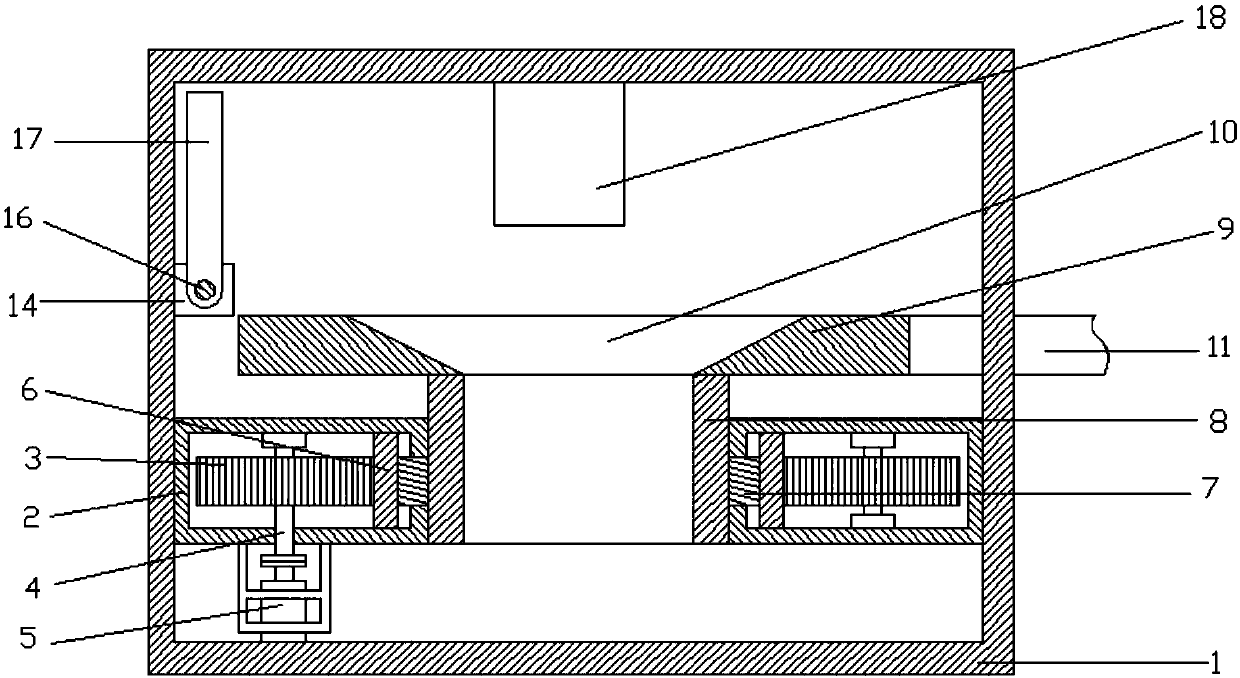
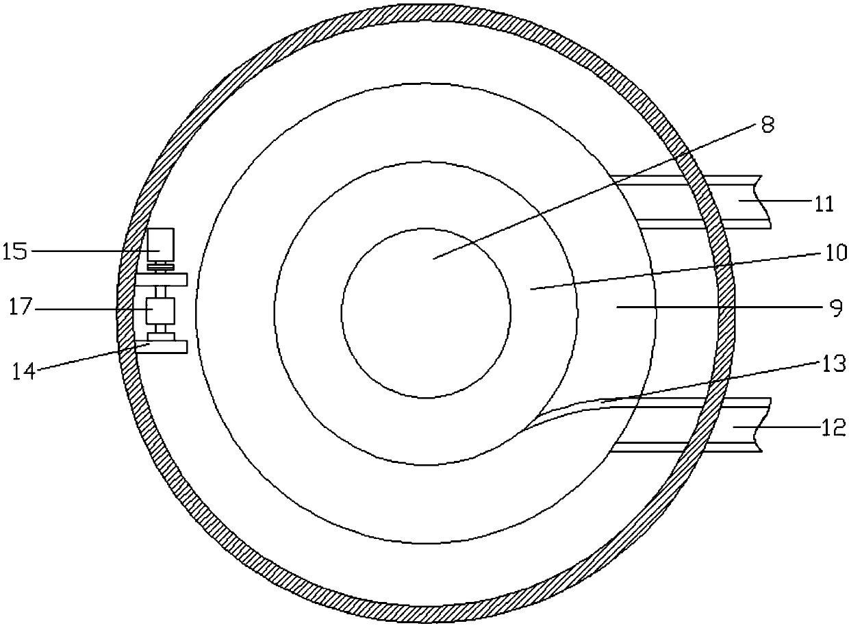
[0025] refer to Figure 1~4 , in an embodiment of the present invention, a drug CT scanning detection device includes a cavity 1, an annular connection groove 2 is fixedly installed at the lower end of the cavity 1, and a first gear 3 is arranged around the interior of the annular connection groove 2, The first gear 3 is connected to the annular connection groove 2 through the first rotating shaft 4, and the first motor 5 is connected to the lower side of the first rotating shaft 4 at the left end through a coupling, and the first motor 5 is connected to the ring through a mounting piece. The slot 2 is connected, the inner side of the first gear 3 is meshed with an external gear 6, the inner side of the external gear 6 is welded with a connecting ring 7, the inner side of the connecting ring 7 is welded with a connecting cylinder 8, and the upper side of the connecting cylinder 8 is fixed Welded with a rotating carrier plate 9, the inside of the rotating carrier plate 9 is pro...
Embodiment 2
[0028] The difference from Embodiment 1 is that mounting plates 14 are provided at the front and rear ends of the left side wall of the cavity 1 located at the left upper end of the rotating bearing plate 9, and a second motor 15 is provided on the rear side of the mounting plate 14. The front side of the second motor 15 is connected with a second rotating shaft 16 through a shaft coupling, and the second rotating shaft 16 is provided with a gear lever 17, and the second rotating shaft 16 is driven to rotate by the second motor 15, so that the gear lever 17 is driven to rotate, The gear bar 17 will be horizontal on the upper side of the rotating carrier plate 9 like this, and after the article will be blocked, it will be discharged through the discharge trough 10 and the connecting cylinder 8, so that the staff can carry out separate inspections, which can effectively carry out drugs. Items are handled very well.
PUM
 Abstract
Description
Claims
Application Information
 - R&D Engineer
- R&D Manager
- IP Professional
- Industry Leading Data Capabilities
- Powerful AI technology
- Patent DNA Extraction
Browse by: Latest US Patents, China's latest patents, Technical Efficacy Thesaurus, Application Domain, Technology Topic, Popular Technical Reports.
© 2024 PatSnap. All rights reserved.Legal|Privacy policy|Modern Slavery Act Transparency Statement|Sitemap|About US| Contact US: help@patsnap.com