
Large portal crane load test device and method

A technology of load test and door crane, which is applied in the direction of measuring devices, machine/structural component testing, instruments, etc., can solve the problems of high cost of experiments, waste of resources, and heavy test configuration, so as to facilitate popularization and use, avoid waste of resources, The effect of reducing the test procedure

Pending Publication Date: 2019-03-29
SINOHYRDO ENG BUREAU 3 CO LTD
View PDF6 Cites 4 Cited by
  • Summary
  • Abstract
  • Description
  • Claims
  • Application Information

AI Technical Summary

Problems solved by technology

[0003] When the existing power station is doing the load test of the door crane and hoist, for the door crane and hoist with small tonnage, most of them use steel wire rope as the main lifting method for the experiment. The method of installing the counterweight, but basically still uses the steel wire rope as the lifting method. Due to the heavy weight of the test, the diameter and type of the steel wire rope are high, the cost is high, the experiment cost is high, the efficiency is low, the steel wire rope is easy to bend and damage, and there is safety. Hidden dangers, and most of the power stations are not universal because of the test equipment. After the test, the test hanger basically has no possibility of next use, resulting in a great waste of resources, especially a large hydropower station, which requires multiple portal cranes and hoists to do the load. Experiments, many projects, heavy workload

Method used


Image

  • Large portal crane load test device and method
  • Large portal crane load test device and method
  • Large portal crane load test device and method

Examples


Embodiment Construction

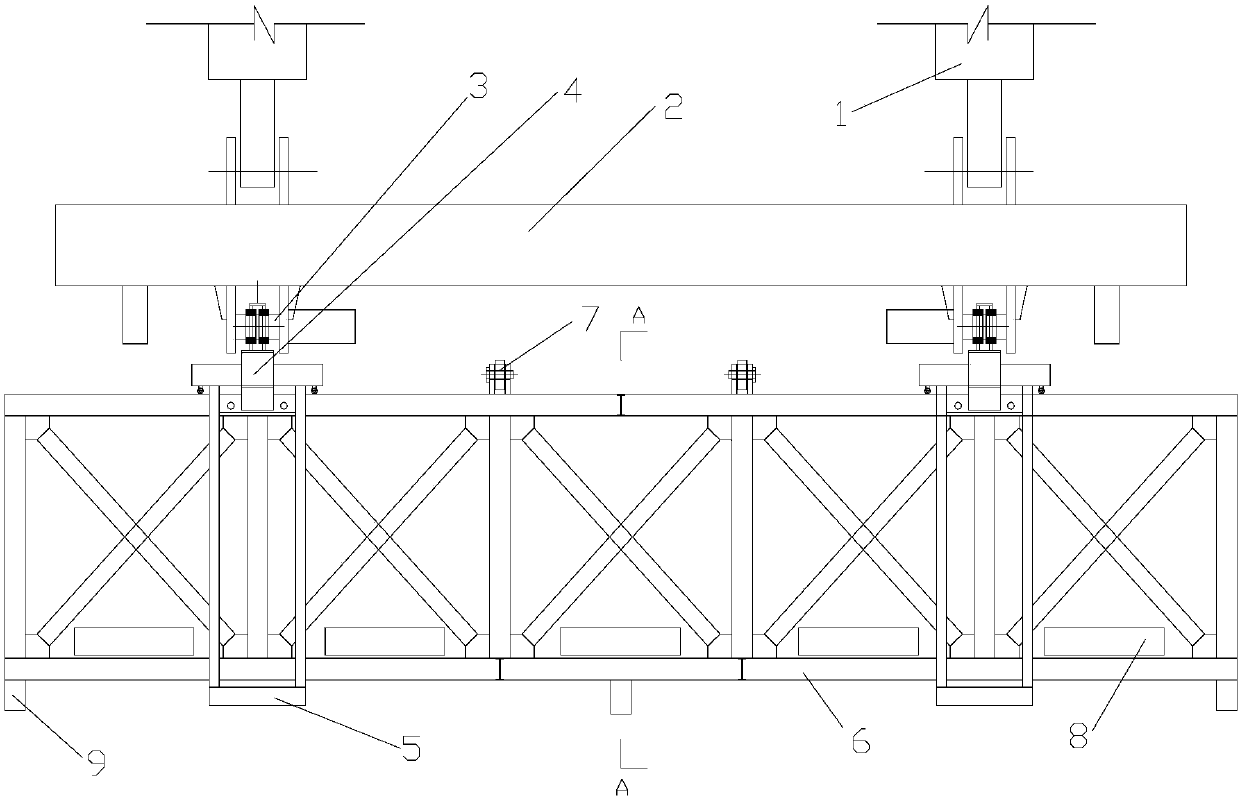
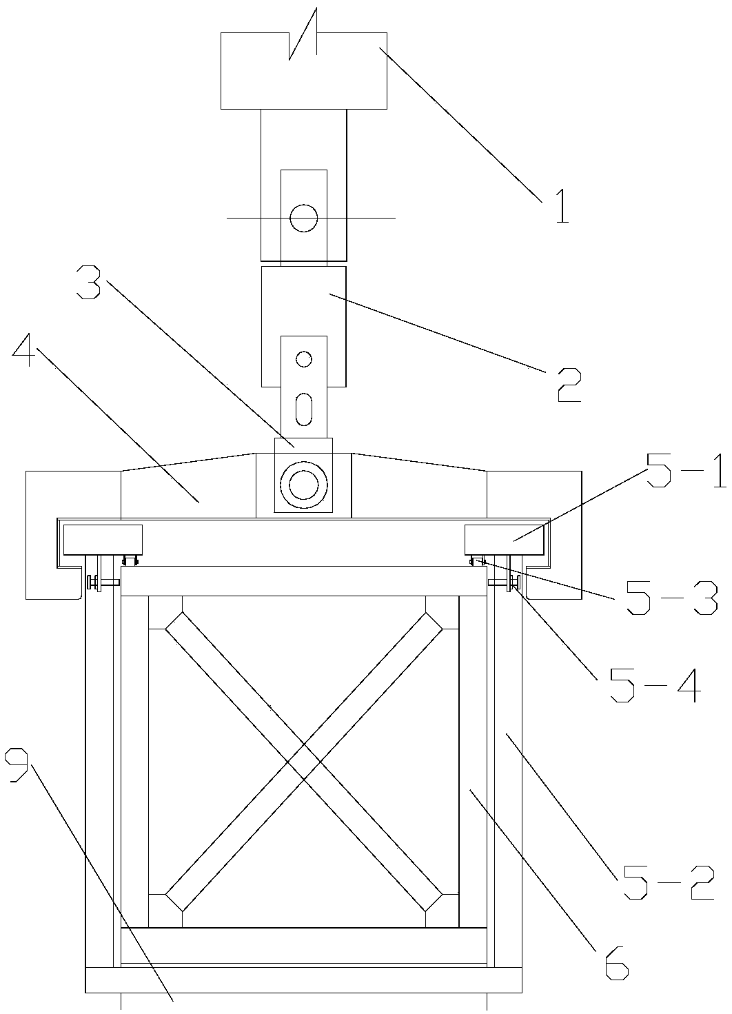
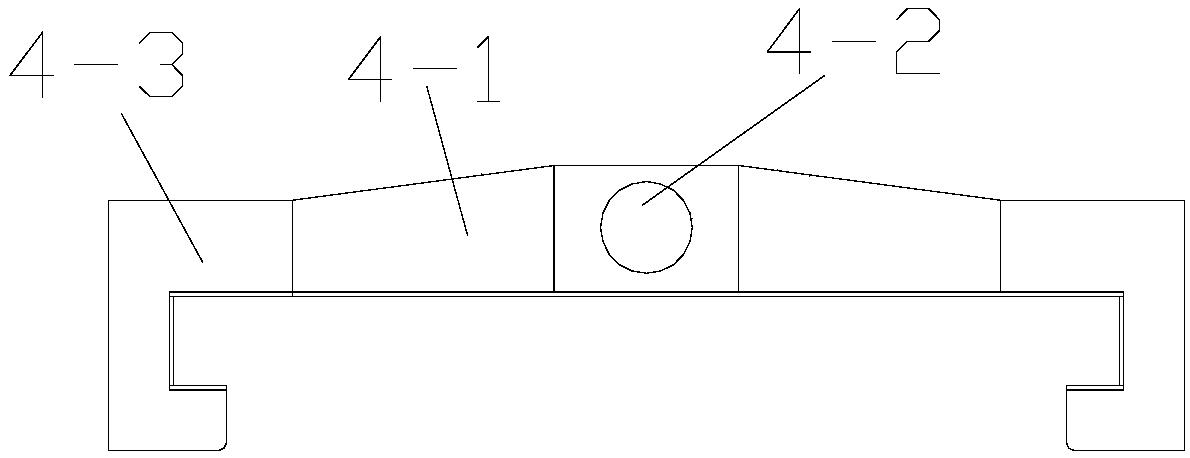
[0049] Such as Figure 1 to Figure 4 As shown, the load test device for a large-scale portal crane according to the present invention includes a main test hanger 6 for bearing test counterweight 8, an outer sliding hanger 5 installed outside the main test hanger 6, and The balance beam 4 outside the sliding hanger 5 and connected with the automatic grab beam 2 of the door machine. The bottom of the test main hanger 6 is installed with a limit mechanism 9 for limiting the moving position of the outer sliding hanger 5, and the door machine automatically grabs the beam The bottom of the 2 is provided with a balance beam connecting pin 3, the top of the automatic grab beam 2 of the door machine is matched with the door motorized pulley group 1. The test main hanger 6 is a cube frame, and the front side, rear side, and left side of the cube frame The upper surface, the right side and the bottom surface are all installed with diagonal supports arranged to cross each other. The top sur...


PUM


Abstract

The invention discloses a large portal crane load test device and method. The device comprises a test main hanging bracket, outer sliding hanging brackets and balance beams connected with a portal crane automatic grabbing beam; and limiting mechanisms are mounted at the bottom of the test main hanging bracket. The method comprises the following steps of 1, determining a test portal crane; 2, mounting the outer sliding hanging brackets; 3, adding a test counterweight for the first time; 4, mounting the balance beams; 5, mounting the balance beams and the portal crane automatic grabbing beam, and completing a first load test; 6, moving out the balance beams; 7, adding a test counterweight again; 8, moving the balance beams inwards and completing the next load test; 9, repeating the steps 6-8for multiple times so as to complete single-item multi-time different load tests; and 10, replacing the test portal crane, and circulating the step 2. The two balance beams are designed to be matchedwith the portal crane automatic grabbing beam to carry out a portal crane load test action; the outer sliding hanging brackets slide on the test main hanging bracket, so that the test requirements ofdifferent grabbing beam sizes are met; and the manual operation is not needed, so that the working efficiency is high.

Description

Technical field [0001] The invention belongs to the technical field of door crane load test, and specifically relates to a large door crane load test device and method. Background technique [0002] Hydropower station hoist is a permanent equipment dedicated to water conservancy and hydropower projects, used to realize the opening and closing of gates, and the lifting and placing of trash racks. According to the type of hoist, it can be divided into fixed hoist hoist, mobile hoist, hydraulic hoist and screw hoist. These equipments need to be subjected to load test before formal use according to the requirements of the specification, especially It is a large-scale mobile door crane and a large-scale hoist. Generally, the rated load of the crane is 300t to 600t, and even some large-scale door cranes have a rated working load of nearly 1000t. According to the requirements of the specification, 25%, 50%, 100%, 125% of the static Load test, as well as 70%, 100%, 110% dynamic load tes...

Claims


Application Information

Patent Timeline
Patent Type & Authority Applications(China)
IPC IPC(8): G01M99/00
CPCG01M99/007
Inventor 杨联东张德华唐鹏程
Owner SINOHYRDO ENG BUREAU 3 CO LTD
Learn More