LED light emitting chip hybrid gear dividing method and application method of light emitting chip

A light-emitting chip and hybrid technology, which is applied in the direction of optical instrument testing, optical performance testing, machine/structural component testing, etc., can solve the problems of many types of LED light-emitting chips, difficulty in merging, and difficulty in management, so as to ensure consistent color purity The effect of high consistency of sex and color purity

Inactive Publication Date: 2019-03-29
CHANGCHUN CEDAR ELECTRONICS TECH CO LTD
View PDF8 Cites 2 Cited by
  • Summary
  • Abstract
  • Description
  • Claims
  • Application Information

AI Technical Summary

Problems solved by technology

[0003] The technical problem to be solved by the present invention is to provide a hybrid binning method for LED light-emitting chips. The color purity of the LED light-emitting chips in the main gear with a large proportion of this method is good, and it is suitable for high-end display screens; at the same time, the proportion is small. The LED light-emitting chips in the scattered files can be used for low-end display screens, which solves the problems of many types of LED light-emitting chips in the scattered files, difficulties in merging, and management difficulties.

Method used


Image

  • LED light emitting chip hybrid gear dividing method and application method of light emitting chip
  • LED light emitting chip hybrid gear dividing method and application method of light emitting chip
  • LED light emitting chip hybrid gear dividing method and application method of light emitting chip

Examples


Embodiment 1

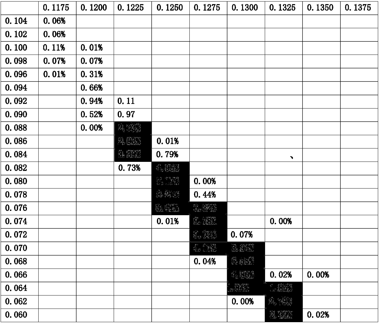
[0046] As shown in Table 1, the first row of numbers represents the upper limit of the x-color coordinates of each gear of the green light-emitting chip, and the x-color coordinate range of each gear is G[x i ~x j ]=0.006; the first column of numbers represents the upper limit of the y color coordinates of each gear of the green light-emitting chip, and the range of the y color coordinates of each gear is G[y i ~y j ]=0.013; there are 9 main stalls of green light-emitting chips; as shown in Table 2, the scattered green light-emitting chips whose x color coordinate is less than or equal to 0.132 are merged into merged file 10, and the scattered green light-emitting chips whose x color coordinate is greater than 0.132 Light-emitting chips are merged into merged file 11. As shown in Table 3, the first row of numbers represents the upper limit of the x color coordinates of each gear of the blue light-emitting chip, and the x color coordinate range of each gear is B[x i ~x j ]=...

Embodiment 2

[0048] When making the display screen, if the green light-emitting chips of the same main file in Table 1 are selected, the blue light-emitting chips of adjacent 2-3 main files in Table 3 can ensure that the green light of the display screen has good consistency and the blue light color is uniform Transitional change.

Embodiment 3

[0050] When making a display screen, select the green light-emitting chip in the merged file 10 or the merged file 11 in Table 2, and select the blue light-emitting chip in the merged file 21 or the merged file 22 in Table 4. Such a display screen has low color purity, but after sufficient There will be no obvious color lumps when stirring. Suitable for low-end display market. The application problem of scattered light-emitting chips is solved.

[0051] Table 1 The proportion of each gear after the green light-emitting chip of a certain specification is graded according to the color coordinates

[0052]

[0053] Table 2 Percentage ranking table of each grade after the green light-emitting chip of a certain specification is graded according to the color coordinates

[0054]

[0055] Table 3 The proportion of each gear after the blue light-emitting chip of a certain specification is graded according to the color coordinates

[0056]

[0057]

[0058] Table 4 Sorti...


PUM


Abstract

The invention relates to an LED light emitting chip hybrid gear dividing method. The method comprises the steps that according to the MacAdam color ellipse wide capacity range combined with the screendisplay effect, the CIE1931 color coordinate range which can be recognized by human eyes of three primary colors is determined, and gears are divided according to the range; light emitting chips areplanned into the corresponding gear according to different color coordinates thereof; the gears are divided into main gears and disperse gears according to the proportion of the number of light emitting chips in each gear, and the light emitting chips in a number of disperse gears are fully mixed and merged into a merged gear; the light emitting chips in the merged gear are placed on a merged gear blue film and provided for a downstream display manufacturer for use in mid-low end displays; and the light emitting chips belonging to the same main gear are placed on the same blue film and provided for a downstream display manufacturer for use in high-end small-pitch displays. According to the invention, the consistency of the color purity of high-end small-pitch displays is high, and the problems of large number, difficult management and poor availability of disperse gears of small share are solved.

Description

technical field [0001] The invention belongs to the technical field of LED flat panel display, and in particular relates to a hybrid binning method of LED light-emitting chips and an application method of the light-emitting chips. Background technique [0002] At present, the light-emitting chips used in LED displays mostly adopt the method of wavelength and brightness classification. Upstream light-emitting chip manufacturers use testing equipment to measure the brightness, wavelength, voltage and other information of the chip, and then place a type of chip that meets the requirements on the same blue film according to customer needs, and provide multiple blue films with the same parameters for display production. Enterprises, these enterprises use the chips on the blue film with the same parameters to make modules and assemble them into a display. The wavelength-brightness binning method widely used in the industry at present has certain limitations, especially on high-de...

Claims


Application Information

Patent Timeline
Patent Type & Authority Applications(China)
IPC IPC(8): G01M11/02
CPCG01M11/00
Inventor 苗静曹慧毛新越陈宇丁铁夫
Owner CHANGCHUN CEDAR ELECTRONICS TECH CO LTD
Why Eureka
Try Eureka