Torque measuring device based on magnetic coupling
A magnetic coupling and torque measurement technology, applied in measuring devices, torque measurement, instruments, etc., can solve the problem of limiting the service life of the conductive slip ring of the rotating shaft, increasing the complexity of the device and the difficulty of installation, and not having the ability to detect torque. value and other issues to achieve the effect of improving reliability, increasing service life, and avoiding mechanical contact
- Summary
- Abstract
- Description
- Claims
- Application Information
AI Technical Summary
Problems solved by technology
Method used
Image

Examples
Embodiment 1
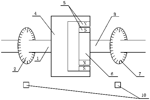
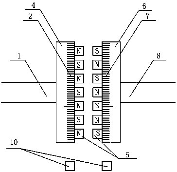
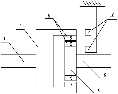
[0024] see figure 1 — Figure 8 , the torque measurement device based on the magnetic coupling, including a driving shaft (8) connected to a driven shaft (1) via a magnetic coupling, the driving shaft (8) is fixedly connected to the driving shaft of the magnetic coupling The rotor (6), the driven shaft (1) is fixedly connected to the driven rotor (4) of the magnetic coupling, the active rotor (8) and the driven rotor (1) are respectively equipped with permanent magnets (5), which are characterized in that : the driving shaft (8) or the driving rotor (6) and the driven shaft (1) or the driven rotor (4) are equipped with an angle measuring device (7,2), and a fixed angle sensor ( 10,9); the magnetic coupling utilizes the interaction of the magnetic field to realize the connection of two independent shafts (8,1) and the transmission of torque on the shaft; due to the transmission of different torques on the two shafts (8,1) There are different angle differences between the magn...
Embodiment 2
[0026] This embodiment is basically the same as Embodiment 1, and the special features are as follows:
[0027] The installation steps of the angle measuring device are as follows: install an angle measuring device on the driving shaft, set a mark on the driven shaft at the same time, and determine the magnitude of the torque by measuring the angular displacement of the mark on the driven shaft relative to the driving shaft. The permanent magnets of the driving rotor and the driven rotor of the coupling are distributed as a radial magnetic field and a transverse magnetic field.
[0028] The installation structure of the angle measuring device is as follows: two angular displacement detection devices are installed on a non-rotating basis, and a mark is respectively set on the driving shaft and the driven shaft at the same time, by measuring the angle of the two marks relative to the non-rotating base The phase difference of the displacement signal is used to determine the angul...
Embodiment 3
[0032] combine figure 1 As shown, the torque measurement device based on the magnetic coupling is a non-contact torque transmission and measurement device, including the driving shaft (8), the driving rotor (6) and the permanent magnet (5) mounted on its surface , the driven rotor (4) and the permanent magnet (5) installed on its surface, the driven shaft (1) and the machine connecting the driven shaft (1), the angular displacement sensing device (2, 7) and the driven rotor Shell part (3). The thickness of the yoke of the driving rotor (6) and the driven rotor (4) is determined according to the actual magnetic field conditions, so as to ensure that most of the magnetic field saturation areas will not appear on the magnetic circuits of the driving rotor (6) and the driven rotor (4) Under the premise, a small part of the saturated magnetic field area is allowed to exist; the thickness of the permanent magnet (5) is selected according to the size of the actual required torque an...
PUM
 Abstract
Description
Claims
Application Information
 - R&D
- Intellectual Property
- Life Sciences
- Materials
- Tech Scout
- Unparalleled Data Quality
- Higher Quality Content
- 60% Fewer Hallucinations
Browse by: Latest US Patents, China's latest patents, Technical Efficacy Thesaurus, Application Domain, Technology Topic, Popular Technical Reports.
© 2025 PatSnap. All rights reserved.Legal|Privacy policy|Modern Slavery Act Transparency Statement|Sitemap|About US| Contact US: help@patsnap.com