Top-lifting charging and replacing system for pure electric heavy-duty vehicles

A pure electric charging and swapping technology, which is applied to vehicle parts, electric power devices, vehicle maintenance, etc., can solve problems such as vibration and bumps, acceleration road conditions, and inconvenient operation, so as to ensure stability, safety, and installation stability Improve and meet the effect of battery life

Pending Publication Date: 2019-03-29
SHANGHAI ENNEAGON ENERGY TECH CO LTD
View PDF0 Cites 16 Cited by
  • Summary
  • Abstract
  • Description
  • Claims
  • Application Information

AI Technical Summary

Problems solved by technology

[0004] In addition, when replacing the battery box of a new energy electric vehicle, especially when it is replaced by hoisting, there are often problems such as difficult positioning or unguaranteed positioning accuracy, resulting in slow battery box replacement and inconvenient operation
At the same time, after the replacement is completed, there may also be problems with insufficient installation stability
New energy electric vehicles often encounter problems such as turning, acceleration, and poor road conditions during driving, which will cause vibration, bumps or shocks during driving. If the battery box is not installed stably enough, it will bring great harm to the stability of the car. In severe cases, it may even make the battery box unable to work or be thrown out directly, which may cause serious traffic accidents

Method used


Image

  • Top-lifting charging and replacing system for pure electric heavy-duty vehicles
  • Top-lifting charging and replacing system for pure electric heavy-duty vehicles
  • Top-lifting charging and replacing system for pure electric heavy-duty vehicles

Examples


Embodiment Construction

[0070] The present invention will be described in detail below in conjunction with specific embodiments. The following examples will help those skilled in the art to further understand the present invention, but do not limit the present invention in any form. Embodiments of the present invention are described in detail below, examples of which are shown in the drawings, wherein the same or similar reference numerals designate the same or similar elements or elements having the same or similar functions throughout. The embodiments described below by referring to the figures are exemplary and are intended to explain the present invention and should not be construed as limiting the present invention.

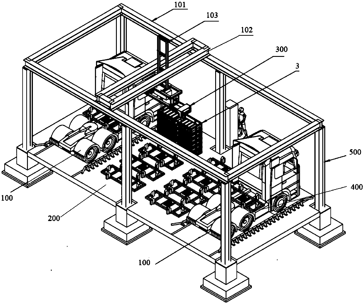
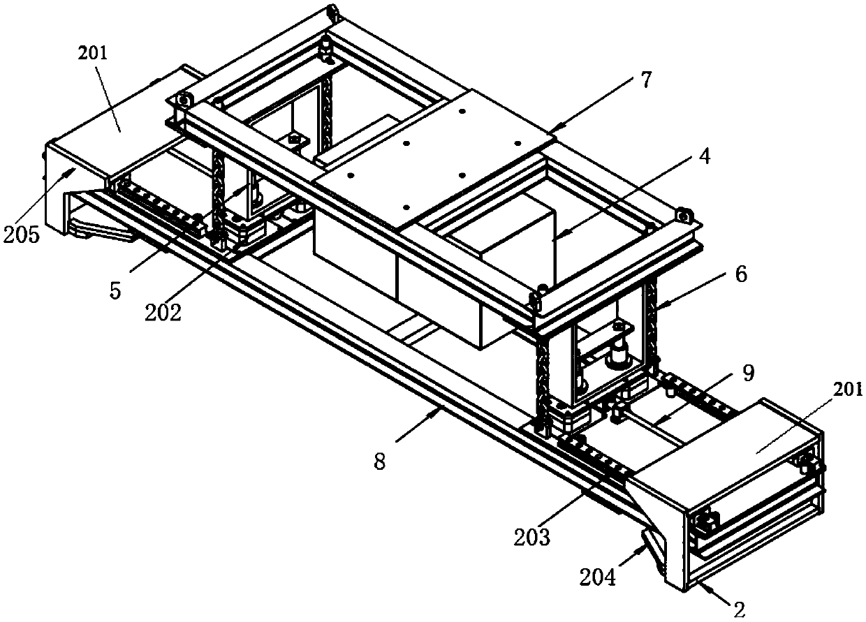
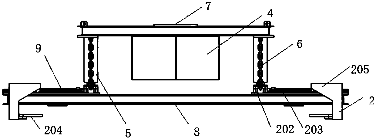
[0071] Such as Figure 1-3 As shown, it is a structural schematic diagram of an embodiment of the top-mounted charging and swapping system for a pure electric heavy-duty vehicle according to the present invention, which includes: a vehicle to be swapped 100, which is provided with...


PUM


Abstract

The invention provides a top-lifting charging and replacing system for pure electric heavy-duty vehicles. The top-lifting charging and replacing system for the pure electric heavy-duty vehicles comprises a vehicle to be subjected to battery replacement, a battery storage area, and an automatic battery-replacing robot; a battery box positioning and locking device is arranged on the vehicle to be subjected to battery replacement; the automatic battery-replacing robot can move freely above the battery storage area and the vehicle to be subjected to battery replacement; after the battery box positioning and locking device of the vehicle to be subjected to battery replacement unlocks the battery box to be replaced, the automatic battery-replacing robot grabs the battery box to be replaced on the vehicle to be subjected to battery replacement from above, and lifts the battery box to be replaced on the vehicle to be subjected to battery replacement into the battery storage area; or, the automatic battery-replacing robot grabs the charged battery box above from the battery storage area, and lifts the charged battery box into the location of the battery box positioning and locking device onthe vehicle to be subjected to battery replacement; and through positioning and locking of the battery box positioning and locking device, the battery box exchange for the vehicle to be subjected tobattery replacement is achieved. The top-lifting charging and replacing system for the pure electric heavy-duty vehicles uses a top-lifting way and can conveniently and quickly complete the charging and replacement of the battery box of new energy vehicles.

Description

technical field [0001] The invention relates to the field of new energy vehicles, in particular to a top-mounted charging and swapping system for a pure electric heavy-duty vehicle. Background technique [0002] In recent years, new energy vehicles have developed rapidly. Electric vehicles relying on batteries as driving energy have no harmful gas emissions and low noise during driving. At present, the main problem affecting the development of electric vehicles is the charging of electric vehicle batteries. Now in new energy The automotive field is gradually improving and popularizing battery charging stations. [0003] In order to further develop and popularize new energy electric vehicles, on the basis of popularizing charging stations for replacing batteries, it is also necessary to solve the problems of battery box replacement speed, convenience, and battery box capacity. Heavy-duty electric vehicles are especially important. [0004] In addition, when replacing the ba...

Claims


Application Information

Patent Timeline
IPC IPC(8): B66C17/26B66C1/12B66C1/28B66C1/66B66C7/08B66C13/04B66C13/12H01M2/10B60S5/06H01M50/20
CPCB66C1/12B66C1/28B66C1/66B66C7/08B66C13/04B66C13/12B66C17/26B60S5/06H01M50/20Y02E60/10
Inventor 张东江翟刚锋来瑞俊唐智翀施亮李倩
Owner SHANGHAI ENNEAGON ENERGY TECH CO LTD
Why Eureka
Try Eureka