SAR differential tomography method and device

An algorithm and matrix technology, applied in the field of SAR differential tomography methods and devices, can solve problems such as large amount of calculation

Inactive Publication Date: 2019-03-26
YUNNAN POWER GRID CO LTD ELECTRIC POWER RES INST
View PDF4 Cites 4 Cited by
  • Summary
  • Abstract
  • Description
  • Claims
  • Application Information

AI Technical Summary

Problems solved by technology

[0005] This application provides a SAR differential analysis method and device, which can solve the disadvantages of large amount of calculation when extracting the tower height and defor

Method used


Image

  • SAR differential tomography method and device
  • SAR differential tomography method and device
  • SAR differential tomography method and device

Examples


Embodiment Construction

[0028] In order to enable those skilled in the art to better understand the technical solutions in the present application, the technical solutions in the embodiments of the present application will be clearly and completely described below in conjunction with the accompanying drawings.

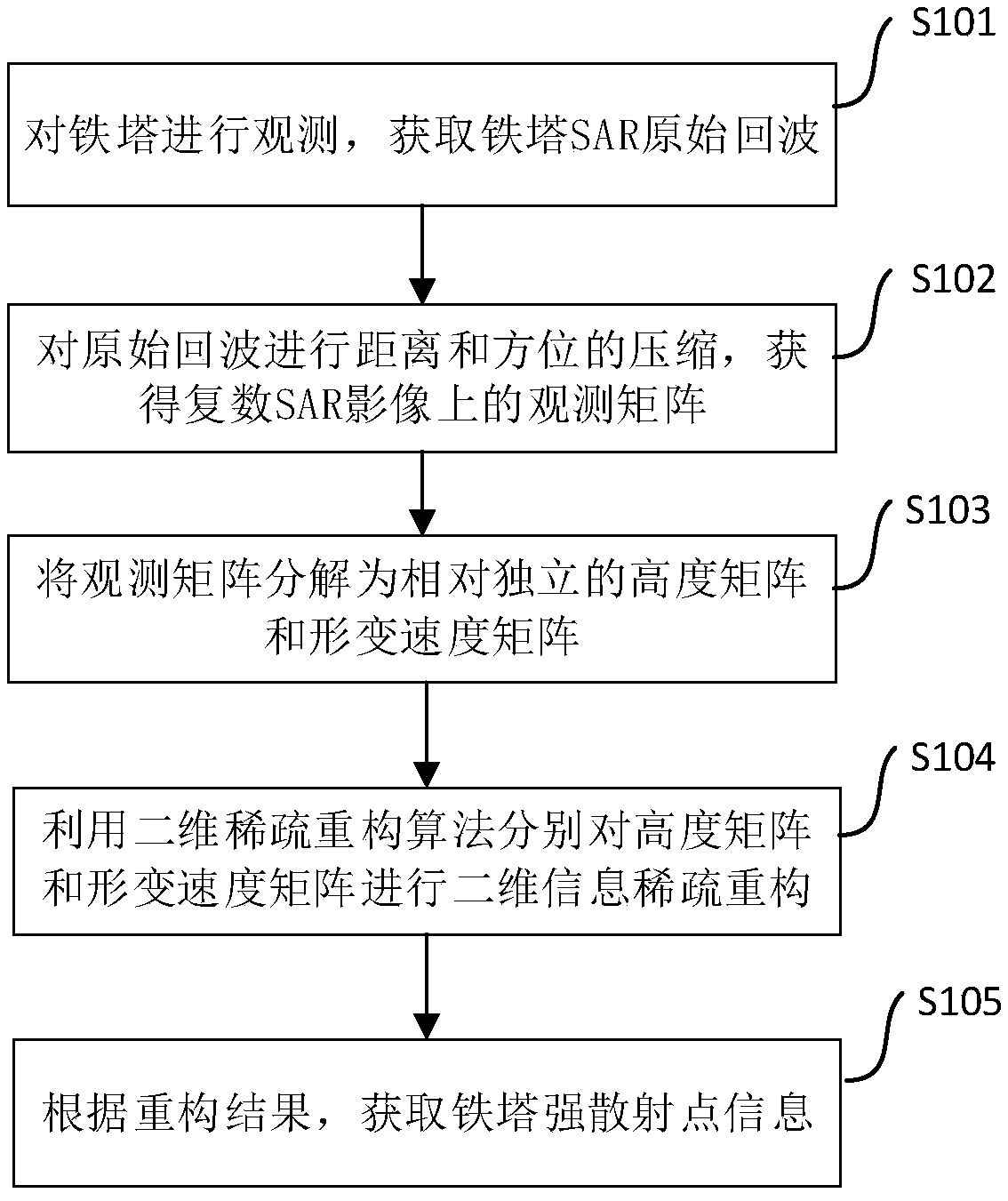
[0029] see figure 1 , the embodiment of the present application provides a SAR differential analysis method, including:

[0030] Step 101, observe the iron tower, and obtain the original SAR echo of the iron tower. The radar technology is used to observe the iron tower. Several radar signals are sent to the same area, and then the echo reflected by the radar signal is obtained, and then the scattering point information of the iron tower is analyzed by using the echo.

[0031] Step 102 , compressing the original echoes in distance and azimuth to obtain observation matrices on complex SAR images, and then obtain complex values. Each observation matrix can be understood as corresponding to a co...


PUM


Abstract

The invention discloses an SAR differential tomography method and device. The method comprises steps that firstly, an iron tower is observed to obtain SAR original echo of the tower; secondly, the distance and the azimuth of the original echo are compressed to obtain an observation matrix of a complex SAR image; thirdly, the observation matrix is decomposed into a height matrix and a deformation velocity matrix which are relatively independent; the two-dimensional sparse reconstruction algorithm is utilized to perform two-dimensional information sparse reconstruction of the height matrix and the deformation velocity matrix respectively; and lastly, according to the reconstruction result, the strong scattering point information of the tower is obtained. The method is advantaged in that thedisadvantage of a large amount of calculation during extraction of the tower height and the deformation rate based on the sparse reconstruction method can be solved, and the practical process of the satellite remote sensing technology in transmission line tower deformation monitoring is promoted.

Description

technical field [0001] The present application relates to the technical field of analysis and measurement control, in particular to a SAR differential analysis method and device. Background technique [0002] The transmission tower is an important part of the transmission line, and its operation status determines the stability and safety of the power system. Therefore, it is necessary to efficiently monitor the 3D image information of the transmission tower in real time, evaluate its stability, and carry out early warning and disposal. Although the traditional Synthetic Aperture Radar (SAR) technology can monitor the target all-weather and all-weather without being restricted by cloud, fog, rain and snow, etc. Due to the superposition of scattering coefficients, there are problems of cylindrical symmetry blur and overlapping, which cause great difficulties in the identification and extraction of targets. In addition, the traditional SAR technology needs to obtain the real ...

Claims


Application Information

Patent Timeline
IPC IPC(8): G01S13/90
CPCG01S13/90G01S13/9029
Inventor 聂鼎黄然周仿荣赵现平沈志方明马仪
Owner YUNNAN POWER GRID CO LTD ELECTRIC POWER RES INST
Why Eureka
Try Eureka