Flying needle test machine

A flying probe testing machine and driving mechanism technology, applied in the field of flying probe testing machines, can solve the problems of time-consuming and labor-intensive, prone to errors, heavy input workload, etc., and achieve the effects of simple operation, improved efficiency, and simplified input methods

Pending Publication Date: 2019-03-26
POLAR LIGHT TECH CO LTD
View PDF0 Cites 0 Cited by
  • Summary
  • Abstract
  • Description
  • Claims
  • Application Information

AI Technical Summary

Problems solved by technology

[0004] The main purpose of the present invention is to provide a flying probe testing machine to solve the problem of time-consuming and labor-intensive replacement of fixtures in the prior art when the fixtures are fixed on the fixture base by screws and when the same set of fixtures is changed to another For the same equipment, the input of the corresponding parameters needs to be manually performed again, which is prone to errors and the input workload is relatively large.

Method used


Image

  • Flying needle test machine
  • Flying needle test machine
  • Flying needle test machine

Examples


Embodiment Construction

[0041] The technical solutions of the present invention will be clearly and completely described below in conjunction with the accompanying drawings. Apparently, the described embodiments are some of the embodiments of the present invention, but not all of them. Based on the embodiments of the present invention, all other embodiments obtained by persons of ordinary skill in the art without making creative efforts belong to the protection scope of the present invention.

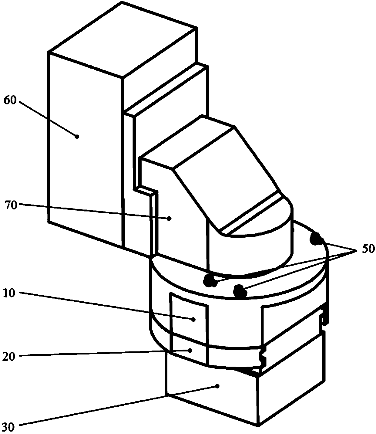
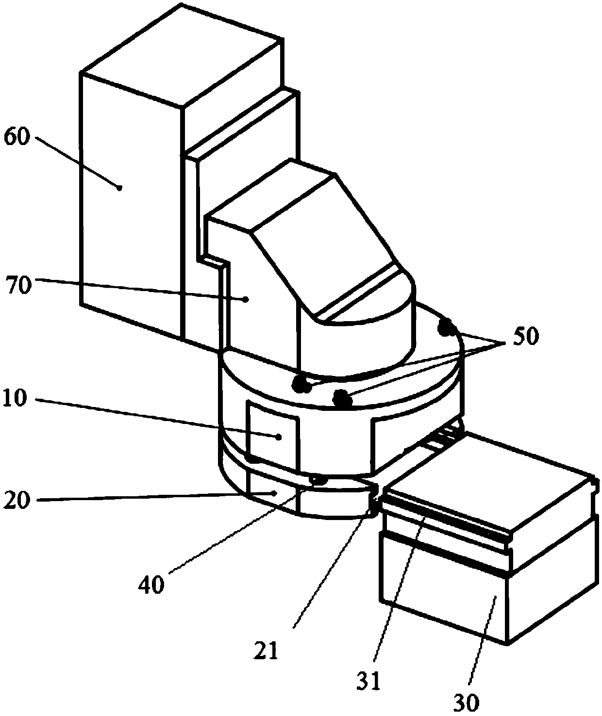
[0042] like figure 1 and figure 2 As shown, the flying probe testing machine of this embodiment includes: a fixture base 10, a driving structure, a clamping structure and a jig 30, the driving structure is arranged on the fixture base 10; the clamping structure is connected with the driving structure, and the clamping structure It has a disassembly position and a working position; when the clamping structure is in the disassembly position, the jig 30 can slide into or out of the clamping structure, and after...


PUM


Abstract

The invention provides a flying needle test machine. The machine comprises a tool, a clamp pedestal, a driving structure, a clamping structure and an RFID chip, wherein the tool is provided with a probe used for detection; the clamp pedestal can removably support the tool; the driving structure is arranged on the clamp pedestal; the clamping structure is connected to the driving structure, and theclamping structure has a dismounting position and a working position; when the clamping structure is located at the dismounting position, the tool can be slide into the clamping structure or be slideout of the clamping structure; after the tool slides into the clamping structure, the driving structure drives the clamping structure to switch from the dismounting position to the working position,and the clamping structure clamps the tool to limit the movement of the tool; and the RFID chip is attached to the outer wall of the tool and is used for storing information input from the outside world in advance. In the prior art, the tool is fixed to the clamp pedestal through a bolt and time consuming and labor consuming are achieved when the tool is replaced; when the same set of tool is replaced to another same equipment, corresponding parameter input needs to be manually performed so that an error is easy to generate and input workload is large. In the invention, the above problems areeffectively solved.

Description

technical field [0001] The invention relates to the technical field of circuit board testing, in particular to a flying probe testing machine. Background technique [0002] At present, in the field of PCB testing, due to the particularity of testing, one or more sets of test fixtures need to be set up separately for each part number. How many test points are there on the PCB, and how many lines are needed to connect the fixture for testing. The test equipment is connected with 32 or 64-bit standard fixtures. If the PCB has 1024 points, 16 are needed. 64-bit jig or 32 32-bit jigs, most of the jigs in actual production are more than 1024 points. In order to test 1024 points on the PCB, fixtures need to be replaced frequently. In the prior art, there are probes on the jig, and the jig is fixed on the jig base by screws, so it is time-consuming and labor-intensive every time the jig is replaced, and the positioning is not accurate, and the fault is high. from time to time. ...

Claims


Application Information

Patent Timeline
Patent Type & Authority Applications(China)
IPC IPC(8): G01R1/073G01R31/28
CPCG01R1/073G01R31/2801
Inventor 黄韬
Owner POLAR LIGHT TECH CO LTD
Why Eureka
Try Eureka