
Transmission reverse gear shaft assembly

A technology of reverse gear shaft and transmission, applied in transmission parts, belts/chains/gears, mechanical equipment, etc., can solve the problem of high cost of thrust needle roller bearings, reduce the risk of wear and ensure sufficient lubrication

Pending Publication Date: 2019-03-26
CHONGQING TSINGSHAN IND
View PDF7 Cites 0 Cited by
  • Summary
  • Abstract
  • Description
  • Claims
  • Application Information

AI Technical Summary

Problems solved by technology

In addition, the cost of thrust needle roller bearings is also higher

Method used


Image

  • Transmission reverse gear shaft assembly
  • Transmission reverse gear shaft assembly
  • Transmission reverse gear shaft assembly

Examples


Embodiment Construction

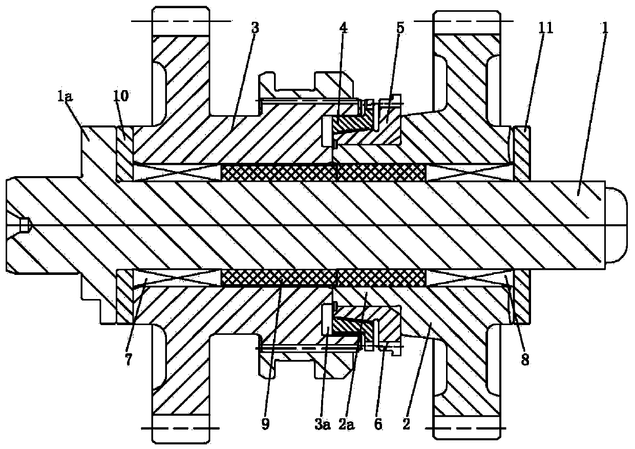
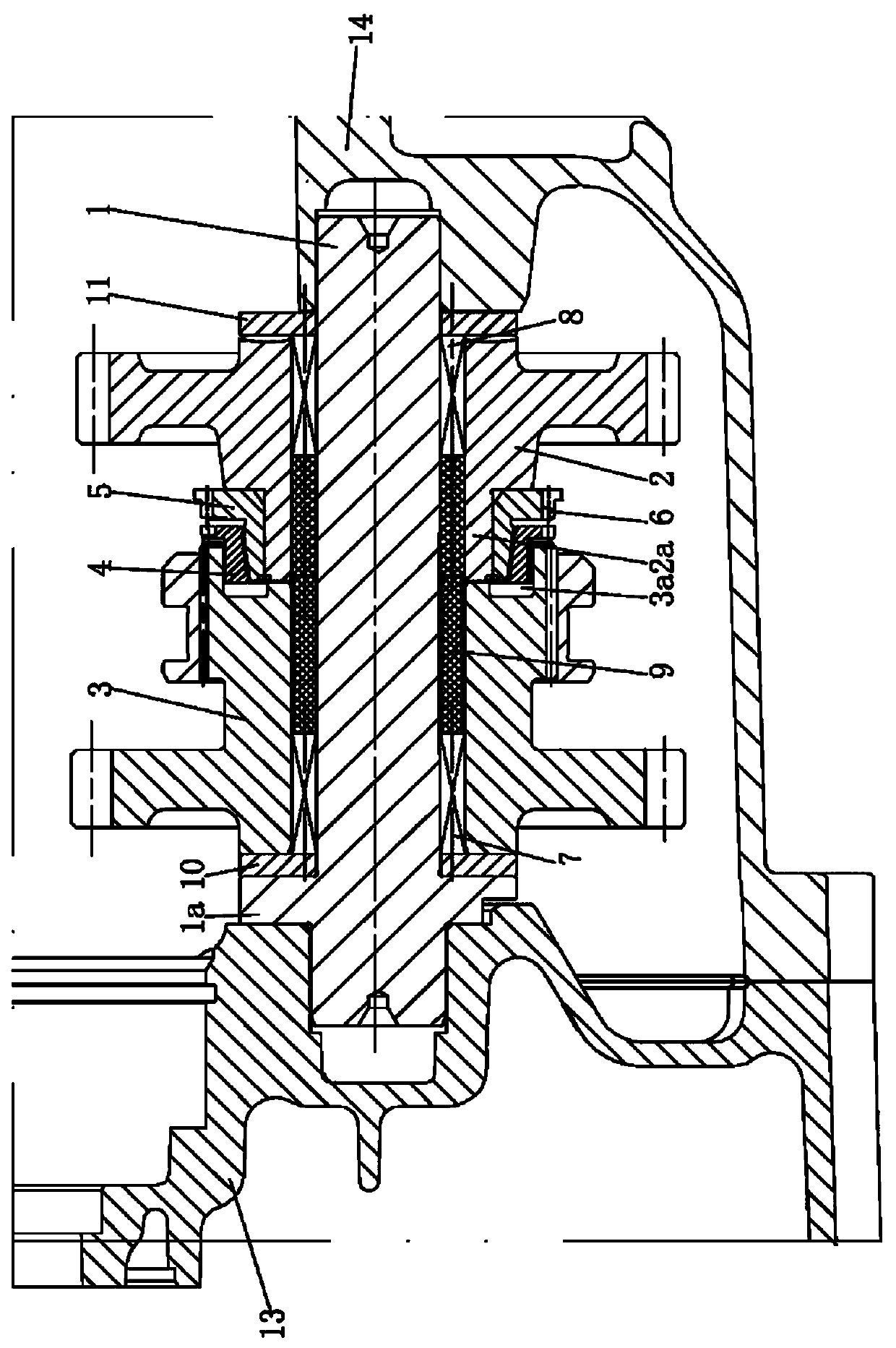
[0029] Such as figure 1 and figure 2 As shown, the transmission reverse gear shaft assembly of the present invention includes a reverse gear shaft 1, a reverse gear assembly, a support assembly, a first wear-resistant gasket 10, and a second wear-resistant gasket 11, and the two ends of the reverse gear shaft 1 are respectively It is connected with the left case body 13 and the right case body 14 of the transmission case, the support assembly is sleeved on the reverse shaft 1, at least a part of the support assembly is connected with the reverse shaft 1, the reverse gear assembly is sleeved on the support assembly, and the reverse At least a portion of the range gear assembly is connected to the support assembly.

[0030] Such as figure 1 and figure 2 The reverse gear assembly shown includes a first gear 2, a second gear 3, a synchronous ring 4, and a synchronous cone hub 5. One end of the first gear 2 is provided with a shaft 2a, and the synchronous cone hub 5 is sleeved...


PUM


Abstract

The invention discloses a transmission reverse gear shaft assembly comprising a reverse gear shaft, a reverse gear gear assembly and a supporting assembly. The supporting assembly is arranged on the reverse gear shaft in a sleeving manner. At least a part of the supporting assembly is connected with the reverse gear shaft. The supporting assembly is sleeved with the reverse gear gear assembly. Atleast a part of the back gear gear assembly is connected with the supporting assembly. The periphery face of one end of the reverse gear shaft is provided with a flange. The transmission reverse gearshaft assembly further comprises a first wear-proof gasket and a second wear-proof gasket. The first wear-proof gasket is arranged on the reverse gear shaft in a sleeving manner and is in clearance fit with the reverse gear shaft. The first wear-proof gasket is located between the flange and one end of the reverse gear gear assembly. The first wear-proof gasket is matched with one end of the backgear gear assembly. The second wear-proof gasket is arranged on the reverse gear shaft in a sleeving manner and is in clearance fit with the reverse gear shaft. The second wear-proof gasket is matchedwith the other end of the back gear gear assembly. The transmission reverse gear shaft assembly has the advantages of lowering assembly difficult and assembly cost.

Description

technical field [0001] The invention relates to the technical field of transmissions, in particular to a reverse gear shaft assembly of a transmission. Background technique [0002] The shaft directly installed on the box body without supporting bearings has a stressed helical gear on the shaft. When the helical gear meshes, an axial force will be generated, and the axial force will cause the end surface of the gear to closely fit with the box body or the shaft end; at the same time, the two There is relative rotation between them, and the mutual rotation under the condition of force will cause the end face of the gear and the end face of the shaft or the end face of the gear and the end face of the box to wear. [0003] For the transmission reverse gear shaft assembly, since the two helical gears on the reverse gear shaft will generate axial force during the process of meshing and transmitting torque, it will cause the end face of the gear and the end face of the shaft or t...

Claims


Application Information

Patent Timeline
Patent Type & Authority Applications(China)
IPC IPC(8): F16H57/023
CPCF16H57/023
Inventor 赵林燕罗朝阳唐云董其慧罗晓娟李小粉苗文慧
Owner CHONGQING TSINGSHAN IND
Learn More