
Plunger pump and engineering machinery

A plunger pump and plunger technology, applied in the field of construction machinery, can solve problems such as the complex structure of the plunger pump, and achieve the effect of improving the complex structure

Active Publication Date: 2019-03-26
XUZHOU HEAVY MASCH CO LTD
View PDF5 Cites 1 Cited by
  • Summary
  • Abstract
  • Description
  • Claims
  • Application Information

AI Technical Summary

Problems solved by technology

[0007] The present invention aims to provide a plunger pump and engineering machinery to improve the problem of complex structure of the plunger pump in the prior art

Method used


Image

  • Plunger pump and engineering machinery
  • Plunger pump and engineering machinery
  • Plunger pump and engineering machinery

Examples


Embodiment Construction

[0056] The following will clearly and completely describe the technical solutions in the embodiments of the present invention with reference to the accompanying drawings in the embodiments of the present invention. Obviously, the described embodiments are only some, not all, embodiments of the present invention. The following description of at least one exemplary embodiment is merely illustrative in nature and in no way taken as limiting the invention, its application or uses. Based on the embodiments of the present invention, all other embodiments obtained by persons of ordinary skill in the art without creative efforts fall within the protection scope of the present invention.

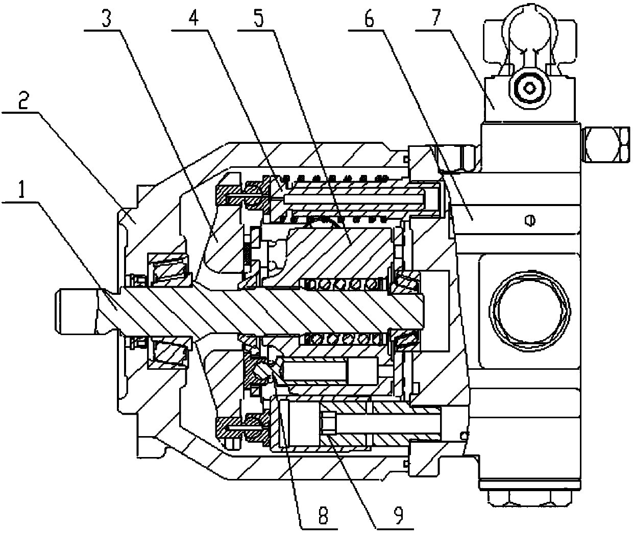
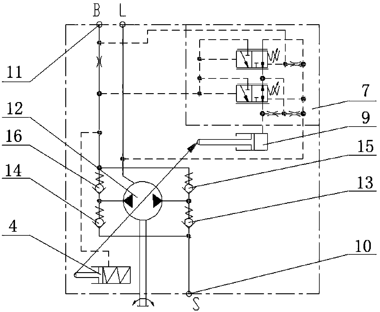
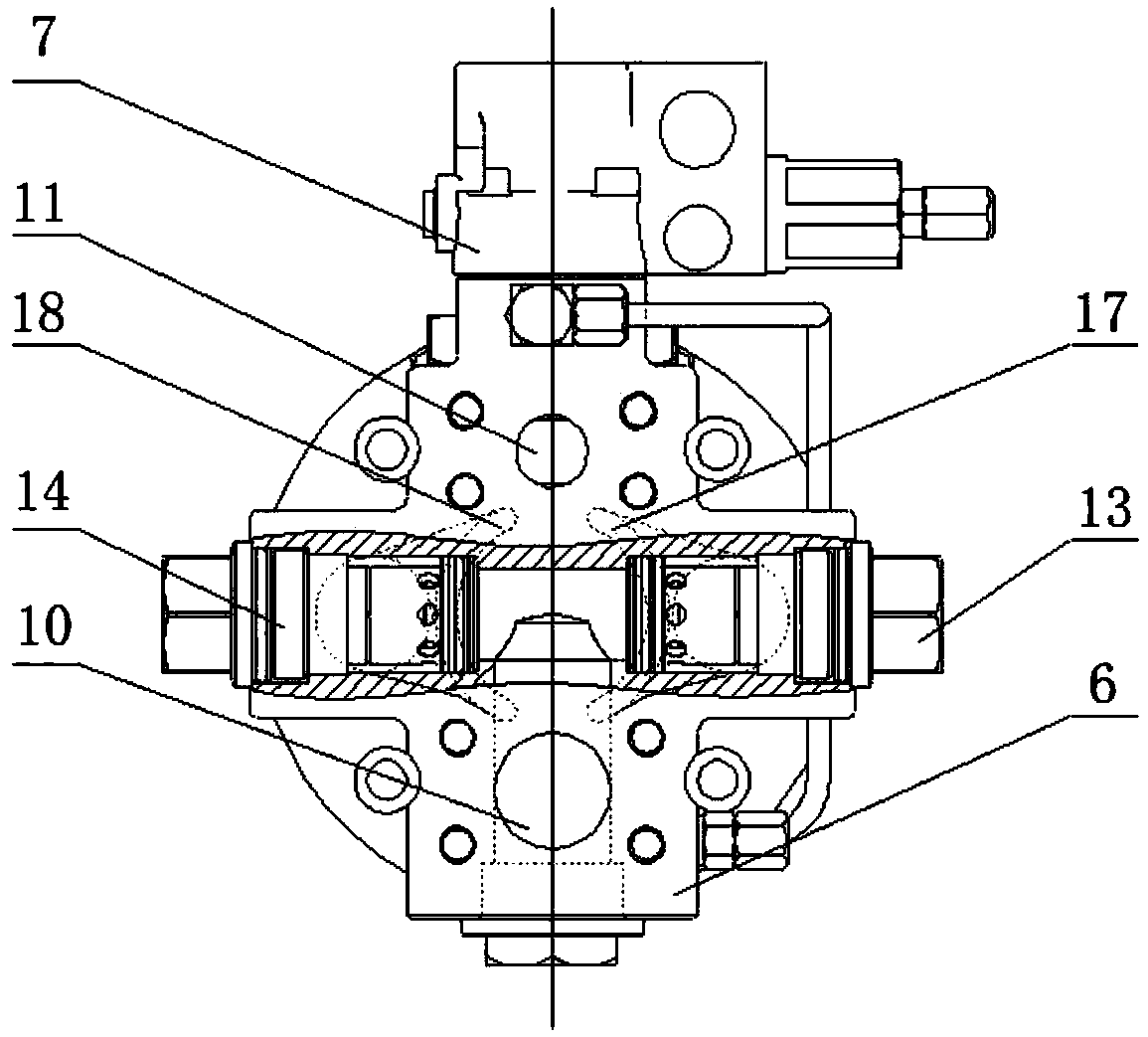
[0057] figure 1 A schematic structural view of the plunger pump of this embodiment is shown; figure 2 A schematic diagram of the plunger pump of this embodiment is shown.

[0058] combine figure 1 and figure 2As shown, the plunger pump of this embodiment includes a housing 2, a cylinder 5 dispo...


PUM


Abstract

The invention relates to a plunger pump and engineering machinery. The plunger pump comprises a shell (2), a cylinder block (5), plungers (8) and an end cover (6), wherein the cylinder block (5) is arranged in the shell (2) and comprises a plurality of plunger holes formed in the circumferential direction of the shell (2); the plungers (8) are arranged in one-to-one correspondence with the plungerholes and can do reciprocating motion in the corresponding plunger holes; one end of the shell (2) is covered with the end cover (6); the end cover (6) is provided with a pore channel communicating with the cylinder block (5) and a valve arranged in the pore channel. The end cover is provided with the pore channel communicating with the cylinder block (5). The valve is arranged in the pore channel. The problems that a plunger pump is complex in structure and large in size in the prior art are improved.

Description

technical field [0001] The invention relates to the field of construction machinery, in particular to a plunger pump and construction machinery. Background technique [0002] A related art plunger pump includes a housing and a pump body provided in the housing. The pump body includes a cylinder with a plunger hole, a rotating shaft for driving the cylinder to rotate, a reciprocating plunger set in the plunger hole, and one end of the cylinder obliquely relative to the axial direction of the cylinder. The swash plate and the elastic part are used to push the plunger towards the swash plate. During the rotation of the cylinder relative to the swash plate, the elastic part can push the plunger towards the outside of the plunger hole so that the plunger hole is drawn out. The hydraulic fluid is sucked, and during the rotation of the cylinder relative to the swash plate, the swash plate can push the plunger toward the inside of the plunger hole to push out the hydraulic fluid in...

Claims


Application Information

Patent Timeline
Patent Type & Authority Applications(China)
IPC IPC(8): F04B1/22F04B1/30F04B1/32F04B53/10F04B53/16
CPCF04B1/2042F04B1/2064F04B1/22F04B1/303F04B1/324
Inventor 胡小冬仲维超杜孝杰杨建春
Owner XUZHOU HEAVY MASCH CO LTD
Learn More