Guide wheel and annular fixture combined barrel longitudinal joint welding equipment

A ring clamp, longitudinal seam welding technology, applied in metal processing equipment, manufacturing tools, workpiece edge parts, etc., can solve the problems of reduced work efficiency, harsh welding conditions, inability to maintain straight lines, etc., to improve work efficiency and avoid rework processing. , the effect of avoiding bias

Active Publication Date: 2019-03-26
浙江欧托电气有限公司
View PDF11 Cites 1 Cited by
  • Summary
  • Abstract
  • Description
  • Claims
  • Application Information

AI Technical Summary

Problems solved by technology

[0005] Aiming at the deficiencies in the prior art, the object of the present invention is to provide a cylinder longitudinal seam welding equipment using guide wheels and ring clamps to solve the problem that the cylinder longitudinal seam welding equipment adopts linear moving welding, so the rigidity requires that the two welding end faces It must be a straight line, and the welding conditions are relatively harsh. Since the welding materials are mostly metal materials, the end face is prone to deviation, and it is often impossible to maintain a straight line, so welding deviation is prone to occur. If the welding end face has a tilt deviation, it is necessary to manually adjust the cylinder to change the welding angle. It is inconvenient to operate and reduces work efficiency

Method used


Image

  • Guide wheel and annular fixture combined barrel longitudinal joint welding equipment
  • Guide wheel and annular fixture combined barrel longitudinal joint welding equipment
  • Guide wheel and annular fixture combined barrel longitudinal joint welding equipment

Examples


Embodiment Construction

[0028] In order to make the technical means, creative features, goals and effects achieved by the present invention easy to understand, the present invention will be further described below in conjunction with specific embodiments.

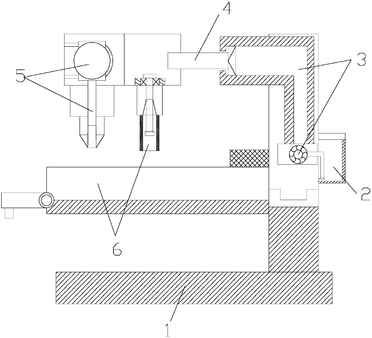
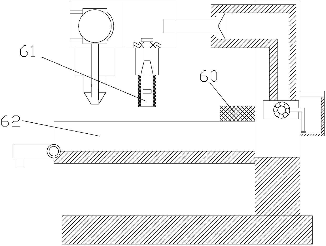
[0029] see figure 1 , the present invention provides a technical scheme of cylinder longitudinal seam welding equipment using guide wheels and ring clamps: its structure includes a base 1, an oil tank 2, a hydraulic expansion seat 3, a piston support rod 4, a welding head 5, and cylinder auxiliary devices 6 , the top of the base 1 is connected to the bottom of the hydraulic expansion seat 3 through slide rails, the left end of the hydraulic expansion seat 3 is fixedly connected to the right end of the cylinder auxiliary device 6, and the top of the cylinder auxiliary device 6 and the inside of the welding head 5 are mechanical connection, the right end of the welding head 5 is embedded with the left end of the piston support rod 4, the right end ...


PUM


Abstract

The invention discloses guide wheel and annular fixture combined barrel longitudinal joint welding equipment. The welding equipment structurally comprises a base, an oil tank, a hydraulic telescopic seat, a piston supporting rod, a welding head and a barrel auxiliary device. Traction electromagnets are electrified to push movable clamping blocks. When the movable clamping blocks get close in pairs, antiskid pads are attached to a barrel, and the barrel is bent to prevent sliding. A retaining ring bar and a locking bar are matched with each other and can achieve the locking effect, strenuous operation during manual bending is reduced, the barrel is clamped to prevent sliding when oppressed and bent, a guide wheel rotates anticlockwise, and cushion pads are squeezed to be matched with deformation blades to rotate clockwise. At the moment, guide wheel springs are squeezed to transfer force to a rotary shaft. The rotary shaft is shaped like a disk. The guide wheel rotates to unload force and keeps a straight line in the moving direction to enable the center of the rotary shaft to be located in the middle of the gap of the end face. The welding head is made to be located in the middle of the gap of the end face all the time when sliding rightwards. The welding effect is greatly improved. Meanwhile, the working efficiency is improved. The phenomenon of rework is avoided.

Description

technical field [0001] The invention relates to a cylinder longitudinal seam welding equipment which utilizes guide wheels and ring clamps, and belongs to the field of welding equipment. Background technique [0002] In reality, metal pipes are generally welded by rectangular plates. One of the welding methods is electrode welding. First, the rectangular plate is concavely folded into a cylindrical shape, and then the gap between the two end faces is welded. However, the current cylinder The longitudinal seam welding equipment adopts linear moving welding, which is fixedly moved from one end to the other end. If the welding end surface has an inclination deviation, it is necessary to manually adjust the cylinder to change the welding angle, which is inconvenient to operate. [0003] However, the existing cylinder longitudinal seam welding equipment has the following disadvantages: [0004] The cylinder longitudinal seam welding equipment adopts linear moving welding, so the...

Claims


Application Information

Patent Timeline
Patent Type & Authority Applications(China)
IPC IPC(8): B23K33/00
CPCB23K33/00
Inventor 刘路宁
Owner 浙江欧托电气有限公司
Why Eureka
Try Eureka