Eureka AIR delivers breakthrough ideas for toughest innovation challenges, trusted by R&D personnel around the world.

emergency respirator

A respirator and top plate technology, applied in the direction of respirators, etc., can solve the problems of unfavorable breathing of emergency patients, delay the best time for rescue, affect the use of respirators, etc., achieve the effect of easy retractable and portable, compact structure, and reduce blockage

Inactive Publication Date: 2020-12-15
QINGDAO MUNICIPAL HOSPITAL
View PDF4 Cites 1 Cited by
  • Summary
  • Abstract
  • Description
  • Claims
  • Application Information

AI Technical Summary

Problems solved by technology

[0002] The simple respirator, also known as the resuscitation ball, is suitable for cardiopulmonary resuscitation and occasions requiring artificial respiration first aid, especially for suffocation, dyspnea or the need to increase oxygen supply. It is easy to use, less painful, fewer complications, and easy to carry , The characteristics of immediate ventilation with or without an oxygen source; the existing respirator generally uses the method of pressing the airbag to inject air into the patient's body, but the general emergency scene environment is relatively harsh, and the airbag is easily broken when it is directly exposed to the air, and the airbag It has a certain service life. When the damaged airbag is not checked out, the emergency respirator cannot be used when it is put into rescue work again, which seriously delays the best time for rescue, and the rescue site with large oily smoke is easy to make the air filter device of the respirator Blockage prevents external air from entering the airbag, and the airbag cannot be reset, which affects the use of the respirator. The air in the rescue site is dry and the air is relatively dry, which is not conducive to the breathing of emergency patients and affects the recovery of patients after emergency rescue.

Method used


Image

  • emergency respirator
  • emergency respirator

Examples


Embodiment Construction

[0014] In order to make the purpose, technical solutions and advantages of the embodiments of the present invention clearer, the technical solutions in the embodiments of the present invention will be clearly and completely described below in conjunction with the drawings in the embodiments of the present invention. Obviously, the described embodiments It is a part of embodiments of the present invention, but not all embodiments. Based on the embodiments of the present invention, all other embodiments obtained by persons of ordinary skill in the art without creative efforts fall within the protection scope of the present invention.

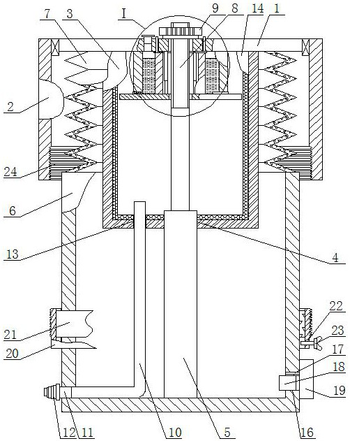
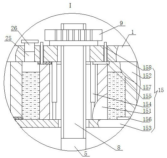
[0015]The emergency respirator, as shown in the figure, includes a top plate 1, the top plate 1 is an annular horizontal plate, the outer peripheral bearing of the top plate 1 is connected to the upper end of the inner wall of the sleeve 2, and the middle of the bottom side of the top plate 1 is fixedly connected to the top side of the filter scree...


PUM


Abstract

An emergency ventilator comprises a top plate, the top plate is an annular horizontal plate, the outer peripheral bearing of the top plate is connected to the upper end of the inner wall of a sleeve,the middle part of the bottom side of the top plate is fixedly connected with the top side of a filter screen, the filter screen is a circular barrel with an open upper end and a closed lower end, a first through hole is arranged in the middle of the bottom side of the filter screen, a first spring rod is movably mounted in the first through hole, and the outer periphery of the first spring rod isin sliding contact fit with the inner wall of the first through hole. The emergency ventilator has the advantages of compact structure, small size, convenience in folding and unfolding, portability,increase of the inspiration power of an airbag through using the spring rod to assist the airbag, avoiding of the airbag from being pressed in an offset manner through the direction guiding effect ofthe spring rod, avoiding of the airbag from being accidentally damaged by the external environment through arranging the airbag in the sleeve, and realization of continuous air inspiration and no affection of the normal use of the ventilator under a damaged airbag condition.

Description

technical field [0001] The invention belongs to the field of breathing assistance devices, in particular to a respirator for first aid. Background technique [0002] The simple respirator, also known as the resuscitation ball, is suitable for cardiopulmonary resuscitation and occasions requiring artificial respiration first aid, especially for suffocation, dyspnea or the need to increase oxygen supply. It is easy to use, less painful, fewer complications, and easy to carry , The characteristics of immediate ventilation with or without an oxygen source; the existing respirator generally uses the method of pressing the airbag to inject air into the patient's body, but the general emergency scene environment is relatively harsh, and the airbag is easily broken when it is directly exposed to the air, and the airbag It has a certain service life. When the damaged airbag is not detected, the emergency respirator cannot be used when it is put into the rescue work again, which serio...

Claims


Application Information

Patent Timeline
Patent Type & Authority Patents(China)
IPC IPC(8): A61M16/16A61M16/10
CPCA61M16/105A61M16/16
Inventor 李廷天黄淑娟李猛孙文欣
Owner QINGDAO MUNICIPAL HOSPITAL
Why Eureka
Eureka Blog
Learn More