Image positioning area selection method and device

A positioning area and image positioning technology, applied in the field of image processing, can solve problems such as low efficiency, too few positioning areas, and inaccurate alignment between the image to be detected and the template image

Active Publication Date: 2021-01-29
BEIJING LUSTER LIGHTTECH
View PDF13 Cites 0 Cited by
  • Summary
  • Abstract
  • Description
  • Claims
  • Application Information

AI Technical Summary

Problems solved by technology

Manual selection of positioning areas requires manual participation, so the efficiency is low, and the positioning quality of the selected positioning areas depends entirely on human industry experience, and the positioning quality cannot be guaranteed. Therefore, at present, software is usually used to automatically select positioning areas
However, in the way of automatically selecting the positioning area, since the selected positioning area needs to meet the preset conditions, it often occurs that the positioning area cannot be selected or the number of the selected positioning areas is too small, which causes the image to be detected and the template image The alignment is not accurate

Method used


Image

  • Image positioning area selection method and device
  • Image positioning area selection method and device
  • Image positioning area selection method and device

Examples


Embodiment Construction

[0089] The following will clearly and completely describe the technical solutions in the embodiments of the present invention with reference to the accompanying drawings in the embodiments of the present invention. Obviously, the described embodiments are part of the embodiments of the present invention, not all of them. Based on the embodiments of the present invention, all other embodiments obtained by persons of ordinary skill in the art without creative efforts fall within the protection scope of the present invention.

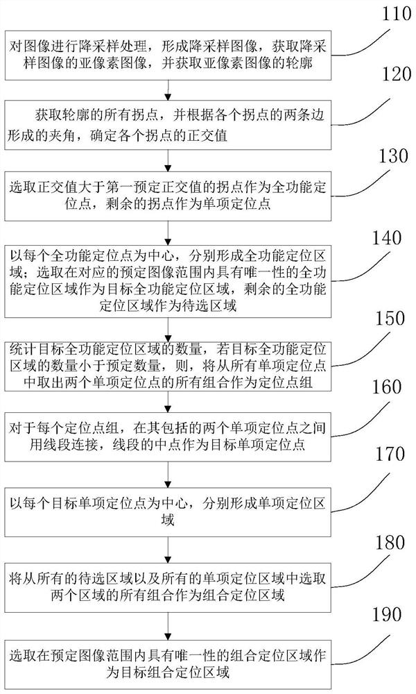
[0090] figure 1A flow chart of a method for selecting an image positioning area according to an embodiment of the present invention is schematically shown.

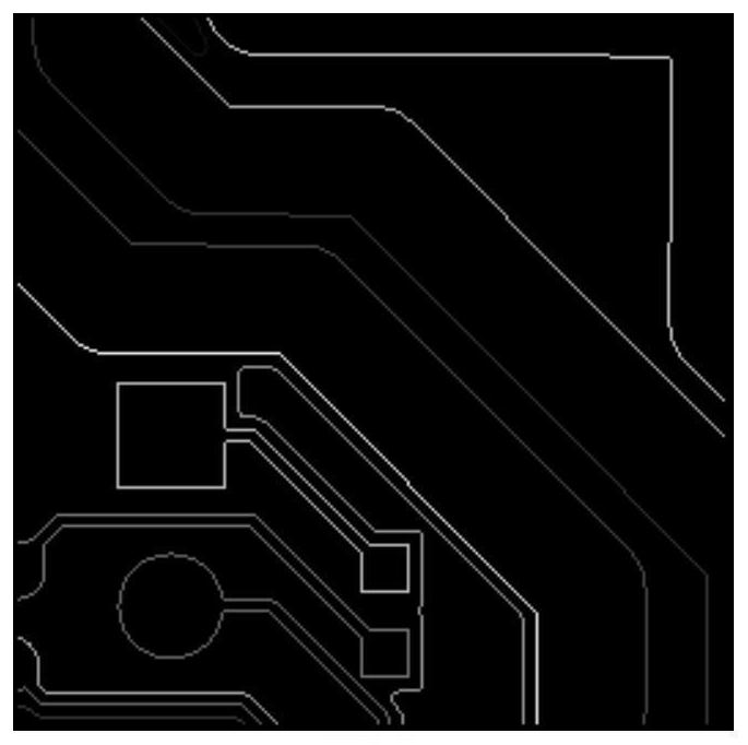
[0091] 110. Perform down-sampling processing on the image to form a down-sampled image, obtain a sub-pixel image of the down-sampled image, and obtain a contour of the sub-pixel image;

[0092] The image here refers to the template image. In AOI technology, it is necessary to align the template image...


PUM


Abstract

The embodiment of the present invention provides a method and device for automatically selecting an image positioning area. First, the target full-function positioning area is automatically selected, and a single target full-function positioning area can realize the positioning of the image in the corresponding predetermined image range, thereby avoiding manual positioning. The quality of the positioning area cannot be guaranteed and the efficiency is low due to the operation. When the target full-function positioning area cannot be selected or the number of selected target full-function positioning areas is not enough, the target combination positioning area including two areas is automatically selected, and the combination of the two areas in the target combination positioning area can realize the corresponding The positioning of the image within the predetermined image range avoids the problem of insufficient image positioning accuracy due to the small number of target full-function positioning areas.

Description

technical field [0001] Embodiments of the present invention relate to the technical field of image processing, and more specifically, to a method and device for selecting an image positioning area. Background technique [0002] AOI (Automatic Optic Inspection) is a technology based on optical principles to detect common defects encountered in soldering products, such as using AOI technology to detect solder joint defects of PCB (Printed Circuit Board, printed circuit board). During AOI inspection, the inspection equipment automatically scans the welding product to be inspected through the camera, collects the image to be inspected, and then compares the parameters of the solder joints in the image to be inspected with the parameters of the corresponding solder joints in the template image to detect the solder joints to be inspected There are defective solder joints on the soldered products. [0003] Due to the influence of optical imaging and other factors in the actual AOI...

Claims


Application Information

Patent Timeline
Patent Type & Authority Patents(China)
IPC IPC(8): G06T7/00G06T7/13
CPCG06T7/001G06T2207/30108G06T7/13
Inventor 孟凡清姚毅刘士清赵敏
Owner BEIJING LUSTER LIGHTTECH
Why Eureka
Try Eureka