Non-contact temporary alignment coupler with strip optical fibers

A ribbon optical fiber, non-contact technology, applied in the coupling of optical waveguide, light guide, optics, etc., can solve the problems of unfavorable construction site use, inconsistent length, time-consuming and laborious cleaning, etc.

Pending Publication Date: 2019-03-22
NANJING JILONG OPTICAL COMM
View PDF0 Cites 0 Cited by
  • Summary
  • Abstract
  • Description
  • Claims
  • Application Information

AI Technical Summary

Problems solved by technology

[0002] The ribbon fiber aligners currently on the market are contacted by two groups of optical fibers, and the temporary coupling effect is achieved through the fiber matching liquid. They belong to the contact fiber coupler. The disadvantages of this contact fiber coupler are mainly It is because the ribbon optical fiber is composed of several (commonly used 4-core, 6-core, 8-core, 12-core) optical fibers arranged regularly. Due to the inconsistent length during the cutting process, the optical fibers on both sides may be distorted when they are connected. Some can be contacted and some cannot be contacted, which will increase the loss of light, and the above-mentioned coupling methods need to be cleaned after use, which is time-consuming and laborious, and there are requirements for the working environment, which is not conducive to the use on the construction site

Method used


Image

  • Non-contact temporary alignment coupler with strip optical fibers
  • Non-contact temporary alignment coupler with strip optical fibers

Examples


Embodiment Construction

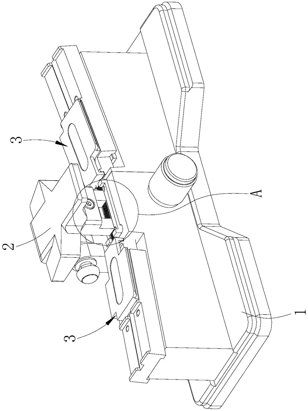
[0015] Such as Figures 1 to 2 shown

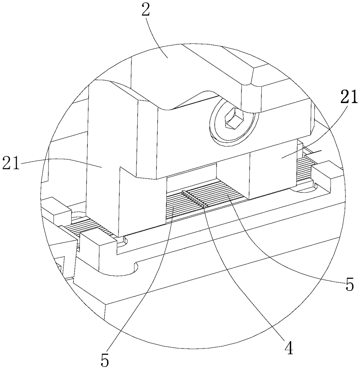
[0016] The coupler includes a base 1 , an indenter 2 , a convex lens array and two fiber holders 3 .

[0017] The base 1 is provided with a mirror groove matching the convex lens array and two positioning grooves for placing the ribbon optical fiber 5. The two positioning grooves are distributed left and right respectively. The mirror groove is between the two positioning grooves. The mirror groove communicates with the two positioning grooves. The center lines of the two positioning slots are collinear, and the extension lines of the center lines of the two positioning slots pass through the mirror slot.

[0018] Two optical fiber clamps 3 are fixed on the base 1, and the two optical fiber clamps 3 correspond to the two positioning grooves (the optical fiber clamp 3 includes a seat body and an upper cover, and the seat body is provided with a groove for positioning the ribbon-shaped optical fiber 5, and the upper cover is hinged on the ...


PUM


Abstract

The invention provides a non-contact temporary alignment coupler with strip optical fibers. The coupler includes a base, a press head and a convex lens array. The base is provided with a lens slot matched with the convex lens array, and two positioning slots containing the strip optical fibers. The lens slot is communicated with the two positioning slots, the center lines of the two positioning slots are collinear, and the extension lines of the center lines of the two positioning grooves pass through the lens slot. The convex lens array is placed in the lens slot, the press head is hinged tothe base for cooperation with the base, and the strip optical fibers placed in the two positioning grooves are clamped and fixed. According to the focusing principle of a convex lens, optical signalsare introduced into one ends of the optical fibers, and the other ends of the optical fibers are connected to a power meter. Through the convex lens array, the light emitted by one strip optical fiberwith the optical signal is output to the other optical fiber after one-to-one focusing. The non-contact alignment and coupling of the strip optical fibers are achieved. The alignment coupler has theadvantages that light loss is small, and the accuracy is high, no matching liquid is needed, and operation is simple and convenient.

Description

technical field [0001] The invention relates to a non-contact temporary alignment coupler for ribbon optical fiber. Background technique [0002] The ribbon fiber aligners currently on the market are contacted by two groups of optical fibers, and the temporary coupling effect is achieved through the fiber matching liquid. They belong to the contact fiber coupler. The disadvantages of this contact fiber coupler are mainly It is because the ribbon optical fiber is composed of several (commonly used 4-core, 6-core, 8-core, 12-core) optical fibers arranged regularly. Due to the inconsistent length during the cutting process, the optical fibers on both sides may be distorted when they are connected. Some can be contacted and some cannot be contacted, which will increase the loss of light, and the above-mentioned coupling methods need to be cleaned after use, which is time-consuming and laborious, and has requirements for the working environment, which is not conducive to the use ...

Claims


Application Information

Patent Timeline
IPC IPC(8): G02B6/32G02B6/36
CPCG02B6/32G02B6/3636
Inventor 张龙程飞方晨之
Owner NANJING JILONG OPTICAL COMM
Why Eureka
Try Eureka