Non-pressurized tool changing device with accurate positioning function

A tool changing device and precise positioning technology, applied in mining equipment, earthwork drilling, tunnels, etc., can solve the problems of unfavorable popularization, difficult tool head replacement, easy dislocation, etc., to save installation and debugging time, prevent dislocation, The effect of reducing the resistance load

Active Publication Date: 2019-03-22
ANHUI TONGDU FLOW TECH
View PDF5 Cites 0 Cited by
  • Summary
  • Abstract
  • Description
  • Claims
  • Application Information

AI Technical Summary

Problems solved by technology

[0006] Aiming at the deficiencies of the prior art, the present invention provides a precisely positioned atmospheric pressure tool changer base, which solves the existing shield machine, which cannot solve the problem of difficulty in replacing the entire tool head and easy misalignment, which is not conducive to popularization and use. question

Method used


Image

  • Non-pressurized tool changing device with accurate positioning function
  • Non-pressurized tool changing device with accurate positioning function
  • Non-pressurized tool changing device with accurate positioning function

Examples


Embodiment Construction

[0030] The following will clearly and completely describe the technical solutions in the embodiments of the present invention with reference to the accompanying drawings in the embodiments of the present invention. Obviously, the described embodiments are only some, not all, embodiments of the present invention.

[0031] In describing the present invention, it should be understood that the terms "center", "longitudinal", "transverse", "length", "width", "thickness", "upper", "lower", "front", " Back", "Left", "Right", "Vertical", "Horizontal", "Top", "Bottom", "Inner", "Outer", "Clockwise", "Counterclockwise", "Axial", The orientation or positional relationship indicated by "radial", "circumferential", etc. is based on the orientation or positional relationship shown in the drawings, and is only for the convenience of describing the present invention and simplifying the description, rather than indicating or implying the referred device or element Must be in a particular orien...


PUM


Abstract

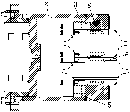
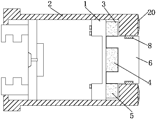
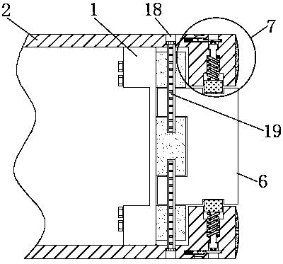
The invention discloses a non-pressurized tool changing device with an accurate positioning function, and relates to the technical field of shield tunneling machines. The non-pressurized tool changingdevice with the accurate positioning function comprises a tool apron and a protection cylinder, the two ends of the tool apron are fixedly connected with the inner surface of the protection cylinderseparately, one side of the tool apron is fixedly connected with one sides of a first fixing block, second fixing block and third fixing block separately, the second fixing block is located in the middle of one side of the tool apron, the first fixing block and the third fixing block are symmetrically distributed at the two sides of the second fixing block, and the other side of the second fixingblock is in fitting connection with the middle of one side of a tool bit. The non-pressurized tool changing device with the accurate positioning function has the advantages that on the one hand, position setting of the first fixing block, second fixing block and third fixing block at one side of the tool apron facilitates positioning of the tool bit, on the other hand, a wedge block of a chuckingdevice is inserted into a clamping groove in the tool bit to rapidly and tightly clamp the tool bit, thereby saving a lot of installation and debugging time.

Description

technical field [0001] The invention relates to the technical field of shield machines, in particular to a precisely positioned base of an atmospheric pressure tool changing device. Background technique [0002] A shield machine is a tunnel boring machine that uses the shield method. The basic working principle of the shield machine is that a cylindrical steel component is pushed forward along the tunnel axis to excavate the soil. The shell of the cylindrical component is the shield, which acts on the excavated unlined tunnel section. As a temporary support, it bears the pressure of the surrounding soil, and sometimes bears the pressure of the groundwater and keeps the groundwater out. Operations such as excavation, soil drainage, and lining are carried out under the cover of the shield. The current shield machine has the problems of insufficient cutting force of the front end cutter, difficulty in replacing the entire cutter head, and easy misalignment. [0003] A shield ...

Claims


Application Information

Patent Timeline
Patent Type & Authority Applications(China)
IPC IPC(8): E21D9/08
CPCE21D9/08Y02P70/10
Inventor 杨凌杰雷鹏王春余宏孝吴劲松陶善祥丁红生
Owner ANHUI TONGDU FLOW TECH
Why Eureka
Try Eureka