
Steel bar bending equipment for building construction

A technology for steel bar bending and building construction, applied in the field of building construction equipment, can solve the problems of reducing the speed of steel bar bending, reducing building construction efficiency, hurting construction personnel, etc. Effect

Inactive Publication Date: 2019-03-22
湖北国丰建设有限公司
View PDF10 Cites 5 Cited by
  • Summary
  • Abstract
  • Description
  • Claims
  • Application Information

AI Technical Summary

Problems solved by technology

[0006] Aiming at the deficiencies of the prior art, the present invention provides a steel bar bending equipment for building construction, which has the advantages of being convenient for bending multiple steel bars at the same time and for fixing the bent steel bars, etc., and solves the problem that the semi-automatic steel bar bending machine only It can bend a steel bar. Due to the large number of steel bars required during construction, the speed of steel bar bending is reduced, thereby reducing the efficiency of construction. Moreover, the semi-automatic steel bar bending machine does not bend the steel bar when bending the steel bar. Fix it so that it is easy to pop out during the bending process, which may hurt the construction personnel

Method used


Image

  • Steel bar bending equipment for building construction
  • Steel bar bending equipment for building construction
  • Steel bar bending equipment for building construction

Examples


Embodiment Construction

[0029] The technical solutions in the embodiments of the present invention will be clearly and completely described below in conjunction with the accompanying drawings in the embodiments of the present invention. Obviously, the described embodiments are only a part of the embodiments of the present invention, rather than all the embodiments. Based on the embodiments of the present invention, all other embodiments obtained by those of ordinary skill in the art without creative work shall fall within the protection scope of the present invention.

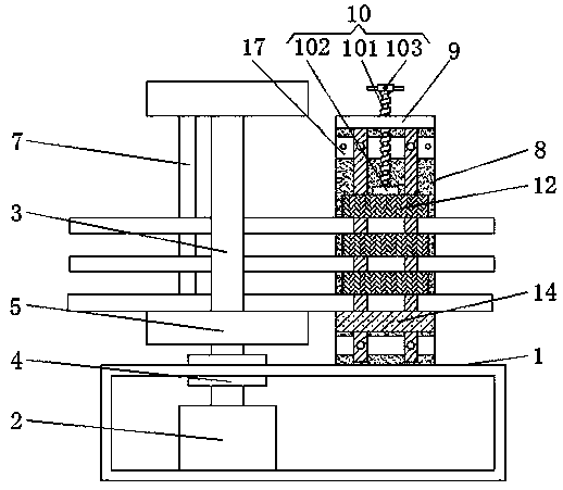
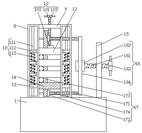
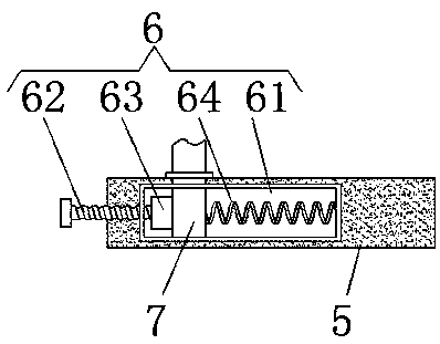
[0030] See Figure 1-6 , A steel bending equipment for construction, including a base 1, a hydraulic rotating cylinder 2 is fixedly installed on one side of the bottom of the inner cavity of the base 1, the top of the hydraulic rotating cylinder 2 is fixed with a supporting shaft 3, and the top of the supporting shaft 3 Extending to the outside of the top of the base 1, the support shaft 3 is fixed with a bearing 4, the outer edge of the...


PUM


Abstract

The invention relates to the technical field of building construction equipment, and discloses steel bar bending equipment for building construction. The steel bar bending equipment for building construction comprises a base, wherein a hydraulic rotating oil cylinder is fixedly mounted on one side of the bottom of a base inner cavity; a supporting shaft is fixedly arranged on the top of the hydraulic rotating oil cylinder in a sleeving mode; the top end of the supporting shaft extends to the outside of the top end of the base; a bearing fixedly sleeves the supporting shaft; and the outer edgeof the bearing is fixedly connected with the top of the base in a sleeved mode. By using the steel bar bending equipment for building construction, one ends of three steel bars are sequentially placedbetween a positioning pressing plate and three moving pressing plates for fixing; the other ends of the three steel bars penetrate between the supporting shaft and a limiting rod, and the three steelbars are bent by rotating of the limiting rod around the supporting shaft; therefore, the three steel bars can be conveniently bent at the same time, the bending speed of the steel bars is increased,and the efficiency of the building construction is improved.

Description

Technical field [0001] The invention relates to the technical field of building construction equipment, in particular to a steel bar bending equipment for building construction. Background technique [0002] Rebar refers to steel for reinforced concrete and prestressed reinforced concrete. Its cross section is round, sometimes square with rounded corners, including round steel bars, ribbed steel bars, and twisted steel bars. They are widely used in the construction field. In construction projects, it is sometimes necessary to use steel bending equipment to bend the original steel bars before use. [0003] In view of the shortcomings of the prior art, the Chinese patent (publication number: CN104226857B) proposes a semi-automatic steel bending machine. The advantages of this semi-automatic steel bending machine are that it has the advantages of increasing the bending work surface of the steel bending machine, simple structure and low modification cost. Other advantages, but there a...

Claims


Application Information

Patent Timeline
Patent Type & Authority Applications(China)
IPC IPC(8): B21F1/00
CPCB21F1/00
Inventor 董立岩
Owner 湖北国丰建设有限公司
Learn More