
Ring-shaped overflow weir with diversion piers

A technology of overflow weirs and diversion piers, which is applied in barrage/weirs, water conservancy projects, sea area projects, etc. It can solve problems such as large fluctuations in reservoir water surface, easy to generate swirl or water fins, and affect discharge capacity. Achieve the effects of improving the flow state of the weir crest, reducing water level fluctuations, and increasing discharge capacity

Pending Publication Date: 2019-03-19
POWERCHINA ZHONGNAN ENG +1
View PDF0 Cites 0 Cited by
  • Summary
  • Abstract
  • Description
  • Claims
  • Application Information

AI Technical Summary

Problems solved by technology

[0002] The vertical shaft spillway is a kind of flood discharge and energy dissipation structure commonly used for damming in canyons with steep bank slopes, or diversion tunnels can be converted into retreat tunnels. Its discharge capacity is the same as that of the entrance ring overflow weir It is closely related. The weir crest elevation of the conventional circular overflow weir is designed at the same height. To improve the flow state at the weir crest, the diversion pier usually added to the weir crest is also designed at the same height. The upper part of the weir body is prone to swirling or The water fins lead to poor water flow at the top of the weir, and the water surface of the reservoir fluctuates greatly, which affects the discharge capacity

Method used


Image

  • Ring-shaped overflow weir with diversion piers
  • Ring-shaped overflow weir with diversion piers
  • Ring-shaped overflow weir with diversion piers

Examples


Embodiment Construction

[0022] The present invention will be described in further detail below in conjunction with the accompanying drawings.

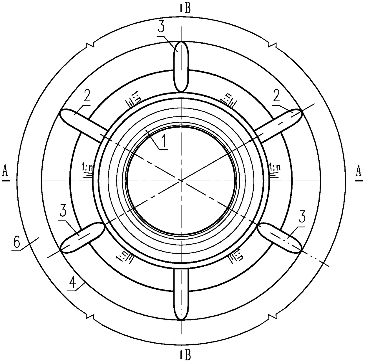
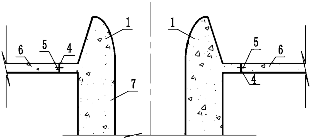
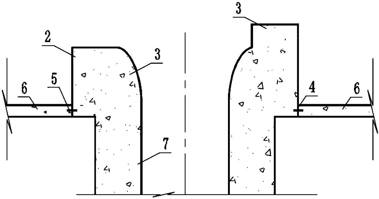
[0023] see Figure 1-3 , an annular overflow weir with a diversion pier, comprising: an annular overflow weir body 1 , a first diversion pier 2 , and a second diversion pier 3 . The ring-shaped overflow weir body is trumpet-shaped, wide at the top and narrow at the bottom. The inner surface is a curved surface formed by a 1 / 4 elliptical line rotating around the central axis of the ring-shaped overflow weir body 1. The outer surface is rotated by a 1:n oblique straight line. The slope surface (the curved surface in the form of the side surface of the cone), where n can be 0.2, 0.3, 0.4 and so on. The inner curved surface of the ring-shaped overflow weir body 1 is guaranteed to be smooth, and the construction of the elliptical curve surface must ensure good smoothness to reduce the negative pressure on the weir surface to the greatest extent. The inner end of ...


PUM


Abstract

The invention discloses a ring-shaped overflow weir with a diversion pier. The ring-shaped overflow weir comprises a ring-shaped overflow weir body and diversion piers evenly distributed on the ring-shaped overflow weir body. The ring-shaped overflow weir body is in a horn shape. The diversion piers include the first diversion piers and the second diversion piers which are arranged alternately. The tops of the second diversion piers are higher than the tops of the first diversion piers. By means of the ring-shaped overflow weir with the diversion piers, the first diversion piers and the seconddiversion piers which are different in height are additionally arranged on the ring-shaped overflow weir, rotational flow on the weir tops can be effectively prevented, the flowing state of the weirtops is improved, inlet reservoir water level fluctuation is reduced, and the discharge capability is improved.

Description

technical field [0001] The invention relates to the technical field of flood discharge and energy dissipation of drop shaft spillways in water conservancy and hydropower projects, and more specifically relates to an annular overflow weir with high and low sill type diversion piers. Background technique [0002] The vertical shaft spillway is a kind of flood discharge and energy dissipation structure commonly used for damming in canyons with steep bank slopes, or diversion tunnels can be converted into retreat tunnels. Its discharge capacity is the same as that of the entrance ring overflow weir It is closely related. The weir crest elevation of the conventional circular overflow weir is designed at the same height. To improve the flow state at the weir crest, the diversion pier usually added to the weir crest is also designed at the same height. The upper part of the weir body is prone to swirling or The water fins lead to poor water flow at the top of the weir and large flu...

Claims


Application Information

Patent Timeline
IPC IPC(8): E02B8/06
CPCE02B8/06
Inventor 叶祥飞章鹏周琦潘定才宿生
Owner POWERCHINA ZHONGNAN ENG
Learn More