
Combined front suspension for engineering vehicle driving cab

A cab and composite technology, applied to the upper structure of the truck, vehicle parts, upper structure, etc., can solve the problem that the elastic element is difficult to adapt to complex working conditions, and achieve the effect of a simple overall structure

Pending Publication Date: 2019-03-19
DONGFENG COMML VEHICLE CO LTD
View PDF0 Cites 4 Cited by
  • Summary
  • Abstract
  • Description
  • Claims
  • Application Information

AI Technical Summary

Problems solved by technology

[0004] The purpose of the present invention is to provide a composite front mount for the cab of an engineering vehicle in view of the problems that the existing engineering vehicle cab front mount uses a single elastic element as the transducer and is difficult to adapt to complex working conditions.

Method used


Image

  • Combined front suspension for engineering vehicle driving cab
  • Combined front suspension for engineering vehicle driving cab

Examples


Embodiment Construction

[0013] The present invention will be further described in detail below in conjunction with the accompanying drawings and specific embodiments.

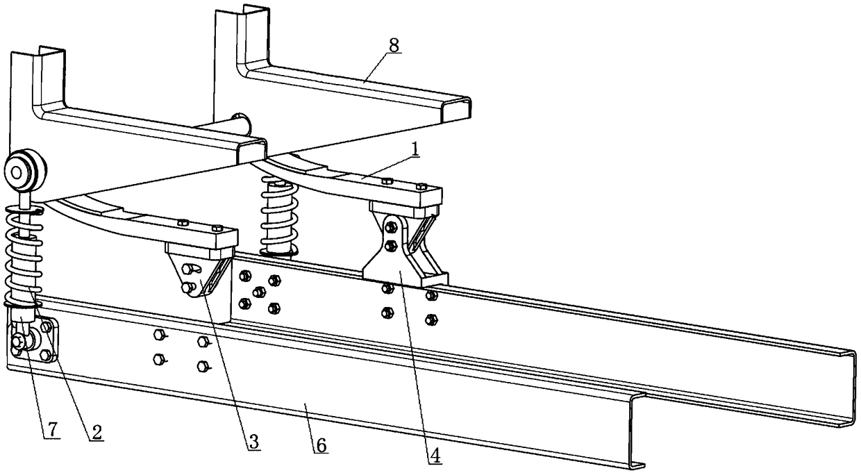
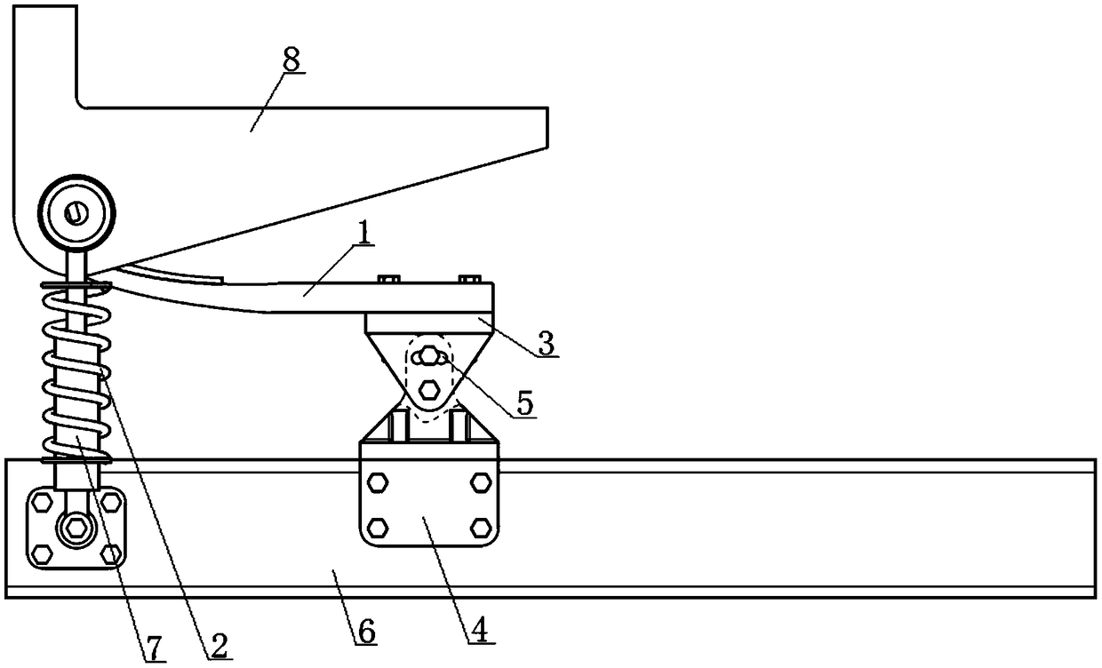
[0014] see Figure 1 to Figure 2 , a composite front suspension for engineering vehicle cab, including leaf spring 1, leaf spring bracket 3, swivel base 4 and coil spring 2. The upper end of the leaf spring 1 is coaxially hinged with the upper end of the coil spring 2, the bottom end of the leaf spring 1 is fixedly connected to the leaf spring support 3 through bolts, and the leaf spring support 3 and the rotating base 4 are hinged through bolts. The swivel base 4 is fixed on the vehicle frame.

[0015] see Figure 1 to Figure 2 , the leaf spring support 3 is processed with an arc chute 5, and the leaf spring support 3 is connected with the rotating base 4 by bolts through the arc chute 5, that is, the leaf spring support 3 can pass through the bolt The arc chute 5 is fixed on the rotating base 4. Here, the circular arc chute 5 is...


PUM


Abstract

A combined front suspension for an engineering vehicle driving cab comprises a plate spring (1), a plate spring support (3), a rotating base (4) and a spiral spring (2). The upper end of the plate spring (1) and that of the spiral spring (2) are coaxially hinged, the bottom end of the plate spring (1) is fixedly connected with the plate spring support (3) through a bolt, the plate spring support (3) and the rotating base (4) are hinged through bolts, and the rotating base (4) is fixed on a vehicle frame. The plate spring (1) only serves as a guide element and does not participate in energy transduction during little displacement on a sound pavement, and energy buffering is performed mainly by the spiral spring (2); under poor working conditions, when the suspension moves and triggers limiting, the plate spring (1) starts to function and cooperate with the spiral spring (2) to participate in kinetic energy buffering so as to adapt to complex working conditions.

Description

technical field [0001] The invention relates to a front mount, more specifically to a composite front mount used for an engineering vehicle cab, and belongs to the technical field of automobiles. Background technique [0002] At present, most of the existing engineering vehicle cab front suspensions use rubber or coil springs as elastic elements, and some foreign models use leaf springs as elastic elements; through the deformation of the above elastic elements, the buffering effect of vibration energy is achieved. [0003] However, due to the complex working conditions of engineering vehicles, it is necessary to run at low speeds in foundation pits or even roadless conditions, and at high speeds on paved roads, and it is difficult to adapt to the above complex working conditions by using a single elastic element as a transducer : 1. The rubber parts have high rigidity and only have a flexible connection function, and basically have no buffering capacity; 2. The coil spring h...

Claims


Application Information

Patent Timeline
IPC IPC(8): B62D33/10B62D33/06
CPCB62D33/0604B62D33/10
Inventor 郭凯陈玲莉吕文兵王鹏奇毛宏泰高传荣石光勇
Owner DONGFENG COMML VEHICLE CO LTD
Learn More